MAIN BODY ECU INSTALLATION

-
INSTALL MAIN BODY ECU (MULTIPLEX NETWORK BODY ECU)
Note
-
Make sure that no foreign matter gets on the connecting surfaces.
-
Do not touch the ECU connector.
-
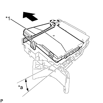
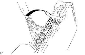
Text in Illustration *1 Housing Sidewall *a 20° Insert the main body ECU (multiplex network body ECU) up to the position where it contacts the housing sidewall of the guide as shown in the illustration.
Tech Tips
Make sure to keep the angle 20° or more as shown in the illustration.
-
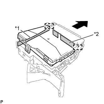
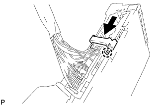
Text in Illustration *1 Housing Sidewall *2 Junction Block Fuse Slide the guide of the main body ECU (multiplex network body ECU) along the housing sidewall so that it contacts the junction block fuses as shown in the illustration.
-
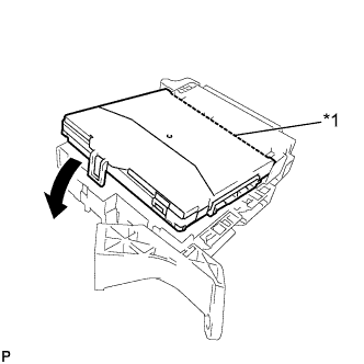
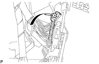
Text in Illustration *1 Side A Contact Portion While keeping the main body ECU (multiplex network body ECU) in contact with side A of the junction block (axis of rotation), rotate it downward as shown in the illustration.
-
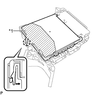
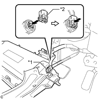
Text in Illustration *1 Push Area Press the push area until the claw engages to install the main body ECU (multiplex network body ECU).
Note
-
Make sure to press only the push area.
-
Confirm the engagement of the main body ECU (multiplex network body ECU) and junction block by listening for the lock sound.
Tech Tips
If a lock sound cannot be heard, visually check the lock part engagement. The engagement can also be confirmed if the main body ECU (multiplex network body ECU) and junction block are flush.
-
-
-
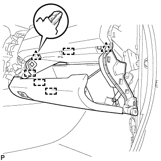
INSTALL INSTRUMENT PANEL JUNCTION BLOCK ASSEMBLY (for LHD)
-
Engage the claw to install the connector as shown in the illustration.
Note
Be sure to engage the connector securely.
-
Engage the claw to lock the connector lock as shown in the illustration.
-
Engage the claw to connect the connector as shown in the illustration.
Note
Be sure to engage the connector securely.
-
Install the instrument panel junction block assembly with the bolt and 2 nuts.
- Torque:
- 8.0 N*m { 82 kgf*cm, 71 in.*lbf }
-
Connect each connector.
Note
Be sure to engage each connector securely.
-
-
INSTALL LOWER NO. 1 INSTRUMENT PANEL AIR BAG ASSEMBLY (for LHD with Driver Side Knee Airbag)
-
Check that the ignition switch is off.
-
Check that the cable is disconnected from the negative (-) battery terminal.
CAUTION:
Wait at least 90 seconds after disconnecting the cable from the negative (-) battery terminal to disable the SRS system.
-
Text in Illustration *1 Airbag Connector *2 Airbag Connector Lock Connect the airbag connector to the lower No. 1 instrument panel airbag assembly.
Note
When connecting any airbag connector, take care not to damage the airbag wire harness.
-
Push in the lock to install the airbag connector.
-
Temporarily install the lower No. 1 instrument panel airbag assembly with the 2 hooks.
-
Engage the 2 claws to install the DLC3.
-
Install the 4 bolts.
- Torque:
- 10 N*m { 102 kgf*cm, 7 ft.*lbf }
Note
Confirm that the lower No. 1 instrument panel airbag assembly is installed securely without any excessive gaps and is not protruding outward.
-
-
INSTALL INSTRUMENT PANEL SUB-ASSEMBLY (for LHD)
-
w/o Driver Side Knee Airbag:
-
Engage the 5 clips and 3 guides.
-
-
w/ Driver Side Knee Airbag:
-
Engage the 4 claws, 7 clips and 3 guides.
-
-
Install the instrument panel sub-assembly with the 2 bolts <B>.
-
-
CONNECT HOOD LOCK CONTROL LEVER SUB-ASSEMBLY (for LHD)
-
Engage the claw and 2 guides to connect the hood lock control lever sub-assembly.
-
-
INSTALL INSTRUMENT SIDE PANEL LH (for LHD)
-
Engage the 3 guides.
-
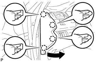
Engage the 4 claws to install the instrument side panel LH as shown in the illustration.
-
-
INSTALL FRONT DOOR OPENING TRIM WEATHERSTRIP LH (for LHD)
-
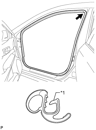
Text in Illustration *1 Alignment Mark (Yellow) Align the alignment mark (Yellow) on the weatherstrip with the protruding portion on the body indicated by the arrow in the illustration, and install the front door opening trim weatherstrip LH.
Note
After installation, check that the corners fit correctly.
-
-
INSTALL COWL SIDE TRIM SUB-ASSEMBLY LH (for LHD)
-
Engage the 2 clips.
-
Install the cowl side trim sub-assembly LH with the clip.
-
-
INSTALL FRONT DOOR SCUFF PLATE LH (for LHD)
-
Engage the 10 claws to install the front door scuff plate LH.
-
-
INSTALL FRONT PANEL GARNISH LH (for LHD)
-
Engage the 3 clips and 8 guides to install the front panel garnish LH.
-
-
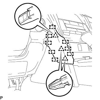
INSTALL INSTRUMENT PANEL JUNCTION BLOCK ASSEMBLY (for RHD)
-
Engage the claw to install the connector as shown in the illustration.
Note
Be sure to engage the connector securely.
-
Engage the claw to lock the connector lock as shown in the illustration.
-
Engage the claw to connect the connector as shown in the illustration.
Note
Be sure to engage the connector securely.
-
Engage the claw to install the wiring harness clamp bracket.
-
Install the nut.
- Torque:
- 8.0 N*m { 82 kgf*cm, 71 in.*lbf }
-
Install the instrument panel junction block assembly with the bolt and nut.
- Torque:
- 8.0 N*m { 82 kgf*cm, 71 in.*lbf }
-
Connect each connector.
Note
Be sure to engage each connector securely.
-
-
INSTALL LOWER INSTRUMENT PANEL SUB-ASSEMBLY (for RHD)
-
Engage the 2 clips and 4 guides.
-
Install the 3 screws <C>.
-
Close the lower instrument panel door.
-
Install the lower instrument panel sub-assembly with the bolt <B> and screws <C>.
-
-
INSTALL NO. 2 INSTRUMENT PANEL UNDER COVER SUB-ASSEMBLY (for RHD)
-
Connect the connector.
-
Engage the 2 guides and 4 claws to install the No. 2 instrument panel under cover sub-assembly.
-
-
INSTALL INSTRUMENT SIDE PANEL LH (for RHD)
-
Engage the 3 guides.
-
Engage the 4 claws to install the instrument side panel LH as shown in the illustration.
-
-
INSTALL FRONT DOOR OPENING TRIM WEATHERSTRIP LH (for RHD)
-
Text in Illustration *1 Alignment Mark (Yellow) Align the alignment mark (Yellow) on the weatherstrip with the protruding portion on the body indicated by the arrow in the illustration, and install the front door opening trim weatherstrip LH.
Note
After installation, check that the corners fit correctly.
-
-
INSTALL COWL SIDE TRIM SUB-ASSEMBLY LH (for RHD)
-
Engage the 2 clips.
-
Install the cowl side trim sub-assembly LH with the clip.
-
-
INSTALL FRONT DOOR SCUFF PLATE LH (for RHD)
-
Engage the 10 claws to install the front door scuff plate LH.
-
-
INSTALL FRONT PANEL GARNISH LH (for RHD)
-
Engage the 3 clips and 8 guides to install the front panel garnish LH.
-
-
CONNECT CABLE TO NEGATIVE BATTERY TERMINAL
Note
When disconnecting the cable, some systems need to be initialized after the cable is reconnected Click here.
-
PERFORM DIAGNOSTIC SYSTEM CHECK
-
Perform diagnostic system check Click here.
-
-
INSPECT SRS WARNING LIGHT