MAIN BODY ECU REMOVAL

-
PRECAUTION
CAUTION:
Be sure to read Precaution thoroughly before servicing Click here.
Note
After turning the ignition switch off, waiting time may be required before disconnecting the cable from the negative (-) battery terminal. Therefore, make sure to read the disconnecting the cable from the negative (-) battery terminal notices before proceeding with work Click here.
-
DISCONNECT CABLE FROM NEGATIVE BATTERY TERMINAL
CAUTION:
Wait at least 90 seconds after disconnecting the cable from the negative (-) battery terminal to disable the SRS system.
Note
When disconnecting the cable, some systems need to be initialized after the cable is reconnected Click here.
-
REMOVE FRONT PANEL GARNISH LH (for LHD)
-
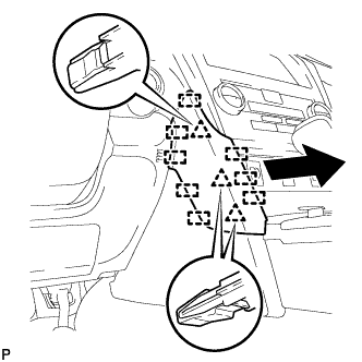
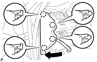
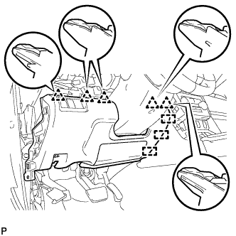
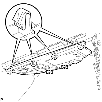
Disengage the 3 clips and 8 guides to remove the front panel garnish LH as shown in the illustration.
-
-
REMOVE FRONT DOOR SCUFF PLATE LH (for LHD)
-
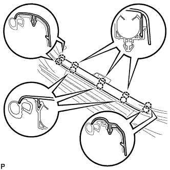
Disengage the 10 claws and remove the front door scuff plate LH.
-
-
REMOVE COWL SIDE TRIM SUB-ASSEMBLY LH (for LHD)
-
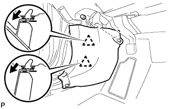
Remove the clip.
-
Disengage the 2 clips and remove the cowl side trim sub-assembly LH.
-
-
DISCONNECT FRONT DOOR OPENING TRIM WEATHERSTRIP LH (for LHD)
-
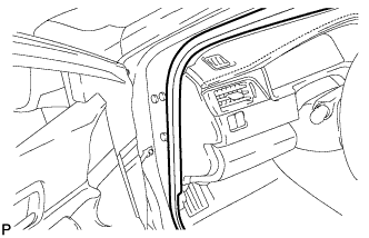
Disconnect the front door opening trim weatherstrip LH.
-
-
REMOVE INSTRUMENT SIDE PANEL LH (for LHD)
-
Using a moulding remover, disengage the 4 claws as shown in the illustration.
-
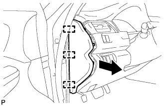
Disengage the 3 guides and remove the instrument side panel LH as shown in the illustration.
-
-
DISCONNECT HOOD LOCK CONTROL LEVER SUB-ASSEMBLY (for LHD)
-
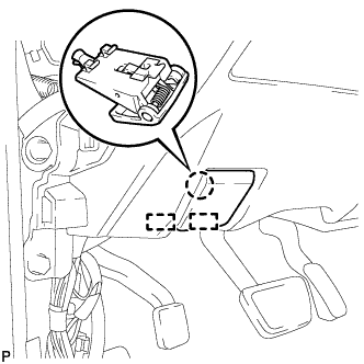
Disengage the claw and 2 guides to disconnect the hood lock control lever sub-assembly.
-
-
REMOVE INSTRUMENT PANEL SUB-ASSEMBLY (for LHD)
-
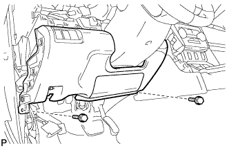
Remove the 2 bolts <B>.
-
w/o Driver Side Knee Airbag:
-
Disengage the 5 clips and 3 guides to remove the instrument panel sub-assembly.
-
-
w/ Driver Side Knee Airbag:
-
Disengage the 4 claws, 7 clips and 3 guides to remove the instrument panel sub-assembly.
-
-
-
REMOVE LOWER NO. 1 INSTRUMENT PANEL AIR BAG ASSEMBLY (for LHD with Driver Side Knee Airbag)
CAUTION:
When storing the lower No. 1 instrument panel airbag assembly, keep the airbag deployment side facing upward.
-
Check that the ignition switch is off.
-
Check that the cable is disconnected from the negative (-) battery terminal.
CAUTION:
Wait at least 90 seconds after disconnecting the cable from the negative (-) battery terminal to disable the SRS system.
-
Remove the 4 bolts.
-
Disengage the 2 claws to disconnect the DLC3.
-
Disengage the 2 hooks to remove the lower No. 1 instrument panel airbag assembly.
Note
When removing the lower No. 1 instrument panel airbag assembly, do not pull the airbag wire harness.
-
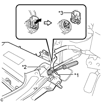
Text in Illustration *1 Protective Tape *2 Airbag Connector *3 Airbag Connector Lock Using a screwdriver with the tip wrapped with protective tape, release the airbag connector lock.
-
Disconnect the airbag connector to remove the lower No. 1 instrument panel airbag assembly.
Note
When disconnecting any airbag connector, take care not to damage the airbag wire harness.
-
-
REMOVE INSTRUMENT PANEL JUNCTION BLOCK ASSEMBLY (for LHD)
-
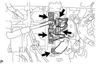
Disconnect the 5 connectors.
-
Remove the bolt, 2 nuts and disconnect the instrument panel junction block assembly.
-
Disengage the claw and disconnect the connector as shown in the illustration.
-
Disengage the claw and release the connector lock as shown in the illustration.
-
Disengage the claw and disconnect the connector as shown in the illustration.
-
Remove the instrument panel junction block assembly.
-
-
REMOVE FRONT PANEL GARNISH LH (for RHD)
-
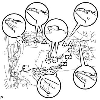
Disengage the 3 clips and 8 guides to remove the front panel garnish LH as shown in the illustration.
-
-
REMOVE FRONT DOOR SCUFF PLATE LH (for RHD)
-
Disengage the 10 claws and remove the front door scuff plate LH.
-
-
REMOVE COWL SIDE TRIM SUB-ASSEMBLY LH (for RHD)
-
Remove the clip.
-
Disengage the 2 clips and remove the cowl side trim sub-assembly LH.
-
-
DISCONNECT FRONT DOOR OPENING TRIM WEATHERSTRIP LH (for RHD)
-
Disconnect the front door opening trim weatherstrip LH.
-
-
REMOVE INSTRUMENT SIDE PANEL LH (for RHD)
-
Using a moulding remover, disengage the 4 claws as shown in the illustration.
-
Disengage the 3 guides and remove the instrument side panel LH as shown in the illustration.
-
-
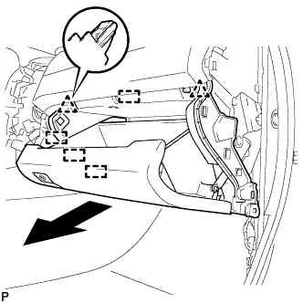
REMOVE NO. 2 INSTRUMENT PANEL UNDER COVER SUB-ASSEMBLY (for RHD)
-
Disengage the 4 claws.
-
Disengage the 2 guides.
-
Disconnect the connector to remove the No. 2 instrument panel under cover sub-assembly.
-
-
REMOVE LOWER INSTRUMENT PANEL SUB-ASSEMBLY (for RHD)
-
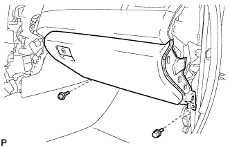
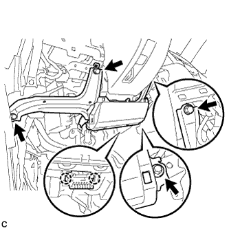
Remove the bolt <B> and screw <C>.
-
Open the lower instrument panel door.
-
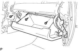
Remove the 3 screws <C>.
-
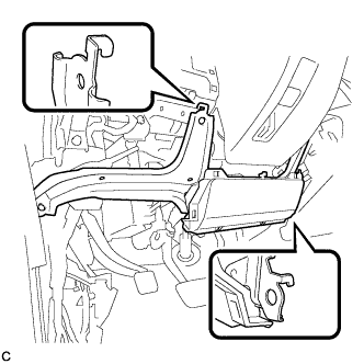
Disengage the 2 clips, 4 guides and remove the lower instrument panel sub-assembly as shown in the illustration.
-
-
REMOVE INSTRUMENT PANEL JUNCTION BLOCK ASSEMBLY (for RHD)
-
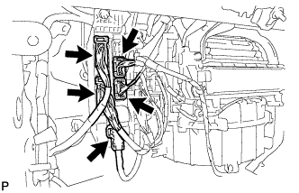
Disconnect the 5 connectors.
-
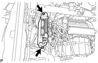
Remove the bolt, nut and disconnect the instrument panel junction block assembly.
-
Remove the nut.
-
Disengage the claw as shown in the illustration and remove the wiring harness clamp bracket.
-
Disengage the claw and disconnect the connector as shown in the illustration.
-
Disengage the claw and release the connector lock as shown in the illustration.
-
Disengage the claw and disconnect the connector as shown in the illustration.
-
Remove the instrument panel junction block assembly.
-
-
REMOVE MAIN BODY ECU (MULTIPLEX NETWORK BODY ECU)
-
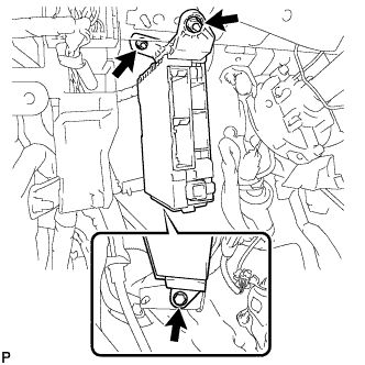
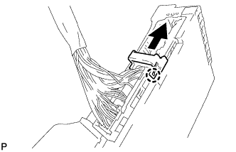
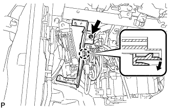
Text in Illustration *1 Main Body ECU (Multiplex Network Body ECU) *2 Claw of Driver Side Junction Block *3 Protective Tape Press the claw of the junction block as shown in the illustration to release the lock.
-
With the junction block lock released, insert a screwdriver with its tip wrapped with protective tape horizontally between the main body ECU (multiplex network body ECU) and junction block.
Note
Use a screwdriver with a diameter of between 5.0 mm (0.197 in.) and 6.3 mm (0.248 in.) and a length of approximately 90 mm (3.54 in.).
-
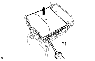
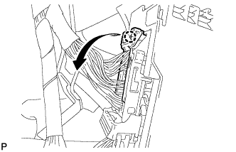
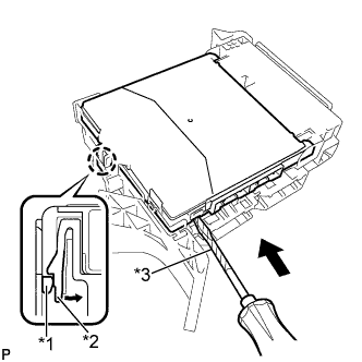
Text in Illustration *1 Protective Tape Using the screwdriver, carefully raise the main body ECU (multiplex network body ECU) up to the position where the connector becomes disengaged.
Note
Do not insert the screwdriver opening between the junction block and the connector of the main body ECU (multiplex network body ECU).
Do not twist the screwdriver to raise the main body ECU (multiplex network body ECU).
-
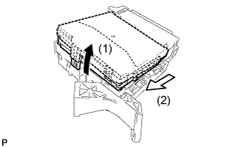
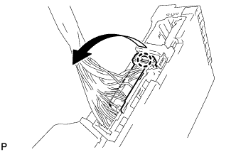
Raise the main body ECU (multiplex network body ECU) as shown by the arrow (1), and then pull it out as shown by the arrow (2) in the illustration.
Note
Do not touch the ECU connector.
-