PARKING ASSIST MONITOR SYSTEM Guide Lines are Displayed with Vehicle Center Line
DESCRIPTION
The rear television camera assembly can create parking guide lines. Because this function is not necessary on vehicles with the parking assist monitor system, the guide line creation function of the rear television camera assembly is disabled.
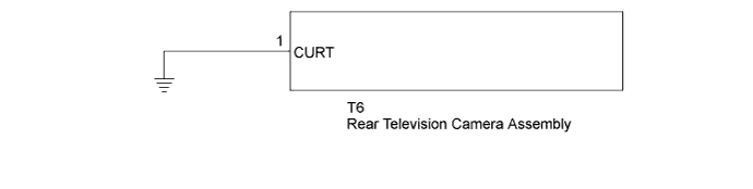
WIRING DIAGRAM
INSPECTION PROCEDURE
PROCEDURE
-
CHECK SCREEN MODE
-
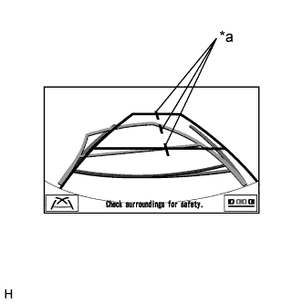
Text in Illustration *a Vehicle Center Line Check the back guide monitor screen.
Result Result Proceed to Guide lines are displayed with vehicle center line. A Guide lines are displayed without vehicle center line. B
B 
USE SIMULATION METHOD TO CHECK (A WIRE MAY BE OPEN) Click here
A 
-
-
CHECK HARNESS AND CONNECTOR (REAR TELEVISION CAMERA ASSEMBLY - BODY GROUND)
-
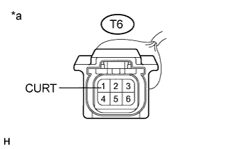
Text in Illustration *a Front view of wire harness connector
(to Rear Television Camera Assembly)
Disconnect the T6 connector from the rear television camera assembly.
-
Measure the resistance according to the value(s) in the table below.
Standard Resistance Tester Connection Condition Specified Condition T6-1 (CURT) - Body ground Always Below 1 Ω
-
NG
REPAIR OR REPLACE HARNESS OR CONNECTOR
OK 
REPLACE REAR TELEVISION CAMERA ASSEMBLY Click here
-