WIPER SWITCH REMOVAL

-
PRECAUTION
Note
After turning the ignition switch off, waiting time may be required before disconnecting the cable from the negative (-) battery terminal. Therefore, make sure to read the disconnecting the cable from the negative (-) battery terminal notices before proceeding with work Click here.
-
DISCONNECT CABLE FROM NEGATIVE BATTERY TERMINAL (for Power Tilt and Power Telescopic Steering Column)
-
Disable the auto tilt away function by changing the customize parameter Click here.
Note
Record the current customize parameter setting (whether the auto tilt away function is enabled or disabled) in order to restore the current setting after finishing this operation.
Tech Tips
Performing the above operation disables the auto tilt away function when the ignition switch is turned off.
-
Turn the ignition switch to ON. Operate the tilt and telescopic switch to fully extend and lower the steering column assembly.
-
Turn the ignition switch off and disconnect the cable from the negative (-) battery terminal.
Note
When disconnecting the cable, some systems need to be initialized after the cable is reconnected Click here.
-
-
REMOVE FRONT DOOR SCUFF PLATE LH (for Power Tilt and Power Telescopic Steering Column)
-
Disengage the 10 claws and remove the front door scuff plate LH.
-
-
REMOVE COWL SIDE TRIM SUB-ASSEMBLY LH (for Power Tilt and Power Telescopic Steering Column)
-
Remove the clip.
-
Disengage the 2 clips and remove the cowl side trim sub-assembly LH.
-
-
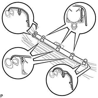
DISCONNECT FRONT DOOR OPENING TRIM WEATHERSTRIP LH (for Power Tilt and Power Telescopic Steering Column)
-
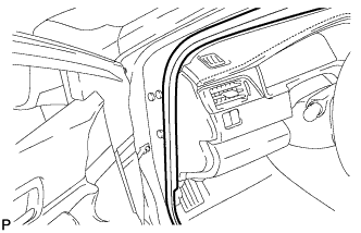
Disconnect the front door opening trim weatherstrip LH.
-
-
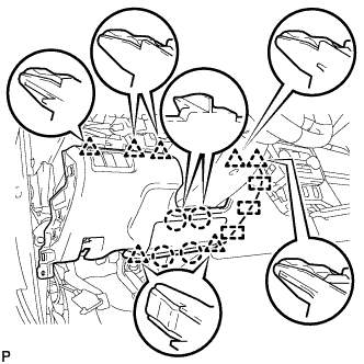
REMOVE INSTRUMENT SIDE PANEL LH (for Power Tilt and Power Telescopic Steering Column)
-
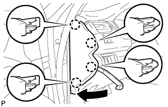
Using a moulding remover, disengage the 4 claws as shown in the illustration.
-
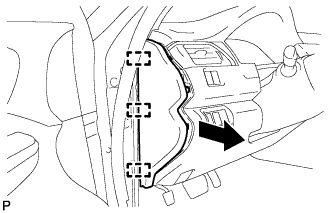
Disengage the 3 guides and remove the instrument side panel LH as shown in the illustration.
-
-
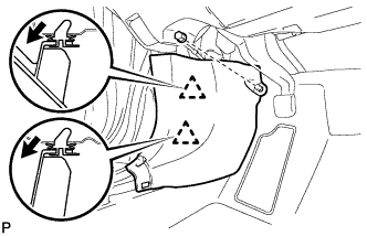
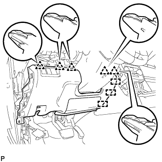
REMOVE FRONT PANEL GARNISH LH (for Power Tilt and Power Telescopic Steering Column)
-
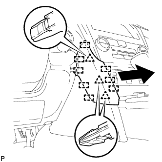
Disengage the 3 clips and 8 guides to remove the front panel garnish LH as shown in the illustration.
-
-
DISCONNECT HOOD LOCK CONTROL LEVER SUB-ASSEMBLY (for Power Tilt and Power Telescopic Steering Column)
-
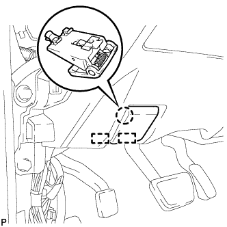
Disengage the claw and 2 guides to disconnect the hood lock control lever sub-assembly.
-
-
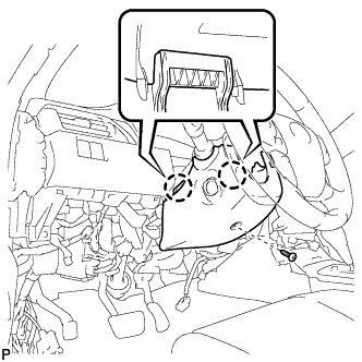
REMOVE INSTRUMENT PANEL SUB-ASSEMBLY (for Power Tilt and Power Telescopic Steering Column)
-
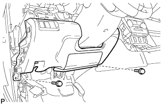
Remove the 2 bolts <B>.
-
w/o Driver Side Knee Airbag:
-
Disengage the 5 clips and 3 guides to remove the instrument panel sub-assembly.
-
-
w/ Driver Side Knee Airbag:
-
Disengage the 4 claws, 7 clips and 3 guides to remove the instrument panel sub-assembly.
-
-
-
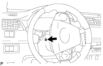
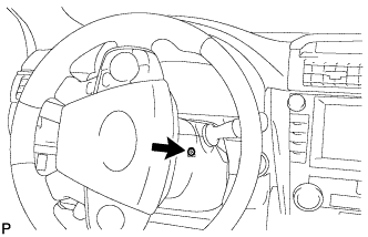
REMOVE LOWER STEERING COLUMN COVER (for Power Tilt and Power Telescopic Steering Column)
-
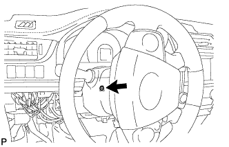
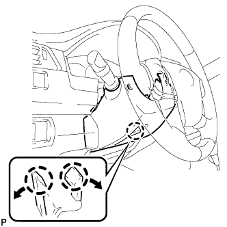
Turn the steering wheel assembly to the left and remove the screw.
-
Turn the steering wheel assembly to the right and remove the screw.
-
Remove the screw.
-
Push the right and left sides of the lower steering column cover to disengage the 2 claws and remove the lower steering column cover.
-
-
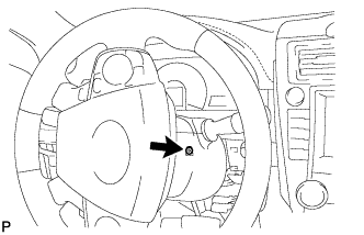
REMOVE LOWER STEERING COLUMN COVER (for Manual Tilt and Manual Telescopic Steering Column)
Note
Removing the lower steering column cover in the incorrect order will cause the parts to break.
-
Release the tilt and telescopic lever, and fully extend and lower the steering column assembly.
-
Lock the tilt and telescopic lever.
-
Turn the steering wheel assembly to the left and remove the screw.
-
Turn the steering wheel assembly to the right and remove the screw.
-
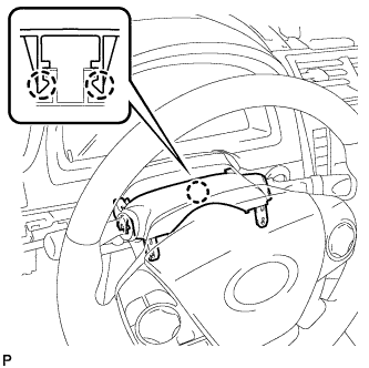
Push the right and left sides of the lower steering column cover to disengage the 2 claws.
-
Insert your fingers into the opening of the tilt lever of the lower steering column cover to disengage the 2 claws.
Tech Tips
Spread the claws to disengage them.
-
-
REMOVE UPPER STEERING COLUMN COVER
-
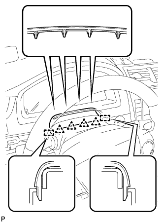
Disengage the 4 clips and 2 guides to separate the instrument cluster finish panel assembly from the upper steering column cover.
-
Disengage the 2 claws and remove the upper steering column cover.
-
-
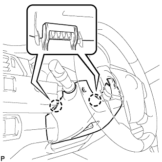
REMOVE WINDSHIELD WIPER SWITCH ASSEMBLY
-
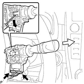
Disconnect each connector.
-
Using a screwdriver, disengage the claw and remove the windshield wiper switch assembly as shown in the illustration.
Note
If the claw is pulled with excessive force, it may break.
-