STEERING GEAR REMOVAL

Note
-
Be sure to align the front wheels straight ahead when removing and installing the steering gear assembly.
-
When disconnecting the steering intermediate shaft assembly and the pinion shaft of the steering gear assembly, be sure to place matchmarks before servicing.
-
PLACE FRONT WHEELS FACING STRAIGHT AHEAD
-
REMOVE FRONT WHEELS
-
SECURE STEERING WHEEL
-
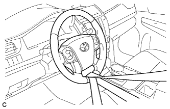
Secure the steering wheel with the seat belt in order to prevent rotation.
Tech Tips
This operation is useful to prevent damage to the spiral cable.
-
-
SEPARATE STEERING INTERMEDIATE SHAFT ASSEMBLY
-
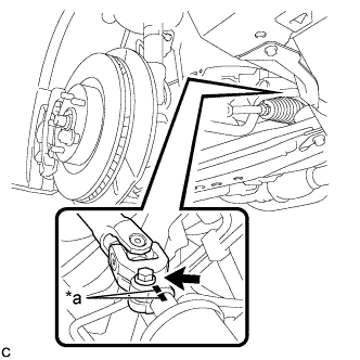
Text in Illustration *a Matchmark Put matchmarks on the steering intermediate shaft assembly and steering link assembly.
-
Remove the bolt.
-
Separate the steering intermediate shaft assembly from the steering link assembly.
-
-
SEPARATE TIE ROD ASSEMBLY LH
-
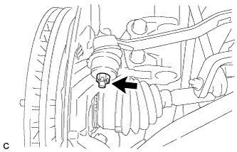
Remove the cotter pin and nut.
-
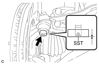
Install SST to the tie rod assembly LH.
- SST
- 09960-20010 ( 09961-02060 )
Note
Make sure that the lower ends of the tie rod assembly LH and SST are aligned.
-
Secure SST using a string.
Note
Be sure to tighten the string firmly to secure SST to the steering knuckle to prevent SST from falling off.
-
Using SST, separate the tie rod assembly LH from the steering knuckle.
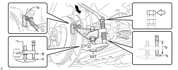
Text in Illustration *1 Center Nut - - *a String *b Grease Application Area 
Place the wrench here. - - - SST
- 09960-20010 ( 09961-02010 )
CAUTION:
Apply grease to the bolt threads and the tip of SST.
Note
-
Install SST with the center nut so that A and B shown in the illustration are parallel. Otherwise, the dust cover may be damaged.
-
Be sure to place the wrench on the part indicated in the illustration.
-
Do not damage the front disc brake dust cover.
-
Do not damage the ball joint dust cover.
-
Do not damage the steering knuckle.
-
-
SEPARATE TIE ROD ASSEMBLY RH
Tech Tips
Perform the same procedure as for the LH side.
-
REMOVE ENGINE ASSEMBLY WITH TRANSAXLE
-
for 2AR-FE: Click here
-
for 2GR-FE: Click here
-
-
REMOVE NO. 1 FRONT STABILIZER BRACKET LH
-
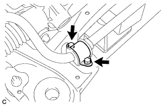
Remove the 2 bolts and front No. 1 stabilizer bracket LH from the front frame assembly.
-
-
REMOVE NO. 1 FRONT STABILIZER BRACKET RH
Tech Tips
Perform the same procedure as for the LH side.
-
REMOVE FRONT STABILIZER BAR
-
Remove the front stabilizer bar from the front frame assembly.
-
-
REMOVE STEERING LINK ASSEMBLY
-
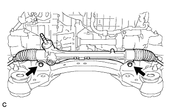
Remove the 2 bolts, 2 nuts and steering link assembly.
Note
Keep the nut from rotating while turning the bolt because the nut has its own stopper.
-
-
SECURE STEERING LINK ASSEMBLY
-
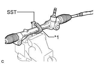
Text in Illustration *1 Protective Tape Using SST, secure the steering link assembly in a vise.
- SST
- 09612-00012
Tech Tips
Tape SST before use.
-
-
REMOVE TIE ROD ASSEMBLY LH
-
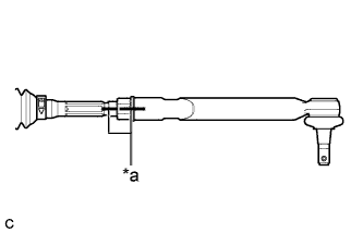
Text in Illustration *a Matchmark Put matchmarks on the tie rod assembly LH and the steering rack end sub-assembly.
-
Remove the tie rod assembly LH and lock nut.
-
-
REMOVE TIE ROD ASSEMBLY RH
Tech Tips
Perform the same procedure as for the LH side.