STEERING COLUMN ASSEMBLY INSTALLATION

-
INSPECT STEERING COLUMN ASSEMBLY
-
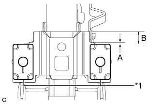
Text in Illustration *1 Capsule Check that the 2 capsules are securely installed to the steering column assembly as shown in the illustration.
Minimum Dimension A B 1 mm (0.0394 in.) 12 mm (0.473 in.) If the capsules are not positioned as specified, replace the electric power steering column sub-assembly with a new one.
-
Check the 2 capsules for deformation and damage.
If either of the capsules is deformed, loose, missing or damaged, replace the electric power steering column sub-assembly with a new one.
-
-
INSTALL STEERING INTERMEDIATE SHAFT ASSEMBLY
-
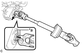
Text in Illustration *a Matchmark Install the steering intermediate shaft assembly to the steering column assembly.
Note
Align the matchmarks on the steering intermediate shaft assembly and the steering column assembly.
-
Install the bolt.
- Torque:
- 35 N*m { 360 kgf*cm, 26 ft.*lbf }
-
-
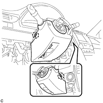
INSTALL STEERING POST ASSEMBLY
-
Install the steering post assembly with the 4 nuts.
- Torque:
- 25 N*m { 255 kgf*cm, 18 ft.*lbf }
-
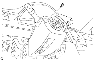
Install the ground wire with the bolt.
- Torque:
- 8.4 N*m { 85 kgf*cm, 74 in.*lbf }
-
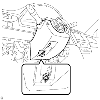
Engage the clamp.
-
Connect the 2 connectors.
-
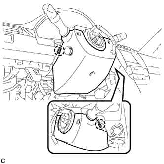
Connect the connectors and engage the wire harness clamps to the steering post assembly.
-
-
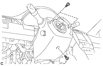
INSTALL NO. 2 AIR DUCT SUB-ASSEMBLY (for LHD)
-
Engage the clamp to install the No. 2 air duct sub-assembly.
-
Engage the 2 claws and guide.
-
Connect the connector to the footwell light.
-
Engage the wire harness clamp to the No. 2 air duct sub-assembly.
-
-
INSTALL NO. 2 AIR DUCT SUB-ASSEMBLY (for RHD)
-
Engage the 2 claws to install the No. 2 air duct sub-assembly.
-
Install the bolt.
- Torque:
- 9.8 N*m { 100 kgf*cm, 87 in.*lbf }
-
Connect the connector to the footwell light.
-
-
CONNECT STEERING INTERMEDIATE SHAFT ASSEMBLY
-
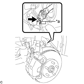
Text in Illustration *a Matchmark Connect the steering intermediate shaft assembly to the steering link assembly.
Note
Align the matchmarks on the steering intermediate shaft assembly and the steering link assembly.
-
Install the bolt.
- Torque:
- 35 N*m { 360 kgf*cm, 26 ft.*lbf }
-
Tighten the clamp.
-
-
INSTALL TURN SIGNAL SWITCH ASSEMBLY WITH SPIRAL CABLE SUB-ASSEMBLY
Note
-
Do not replace the spiral cable with the battery connected and the ignition switch ON.
-
Do not rotate the spiral cable without the steering wheel with the battery connected and the ignition switch ON.
-
Ensure that the steering wheel is installed and aligned straight when inspecting the steering sensor.
-
Engage the 3 claws to install the turn signal switch assembly with spiral cable sub-assembly to the steering post assembly.
-
Connect the connectors to the turn signal switch assembly with spiral cable sub-assembly.
-
-
INSTALL UPPER STEERING COLUMN COVER
-
Engage the 2 claws to install the upper steering column cover.
-
Engage the 4 clips and 2 guides to the upper steering column cover.
-
-
INSTALL LOWER STEERING COLUMN COVER (for Manual Tilt and Manual Telescopic Steering Column)
-
Engage the 2 claws to install the lower steering column cover.
-
Install the 2 screws.
- Torque:
- 2.0 N*m { 20 kgf*cm, 18 in.*lbf }
-
Engage the claw.
-
-
INSTALL LOWER STEERING COLUMN COVER (for Power Tilt and Power Telescopic Steering Column)
-
Engage the 2 claws to install the lower steering column cover.
-
Install the 3 screws.
- Torque:
- 2.0 N*m { 20 kgf*cm, 18 in.*lbf }
-
-
INSTALL INSTRUMENT PANEL SUB-ASSEMBLY (w/o Driver Side Knee Airbag)
-
w/o Driver Side Knee Airbag:
-
Engage the 5 clips and 3 guides.
-
-
w/ Driver Side Knee Airbag:
-
Engage the 4 claws, 7 clips and 3 guides.
-
-
Install the instrument panel sub-assembly with the 2 bolts <B>.
-
-
CONNECT HOOD LOCK CONTROL LEVER SUB-ASSEMBLY (w/o Driver Side Knee Airbag)
-
Engage the claw and 2 guides to connect the hood lock control lever sub-assembly.
-
-
INSTALL INSTRUMENT SIDE PANEL (w/o Driver Side Knee Airbag)
-
Engage the 3 guides.
-
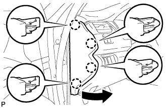
Engage the 4 claws to install the instrument side panel LH as shown in the illustration.
-
-
INSTALL FRONT DOOR OPENING TRIM WEATHERSTRIP (w/o Driver Side Knee Airbag)
-
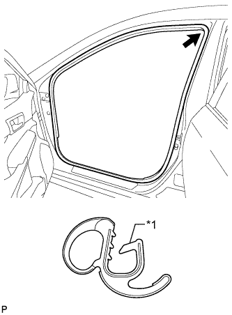
Text in Illustration *1 Alignment Mark (Yellow) Align the alignment mark (Yellow) on the weatherstrip with the protruding portion on the body indicated by the arrow in the illustration, and install the front door opening trim weatherstrip LH.
Note
After installation, check that the corners fit correctly.
-
-
INSTALL COWL SIDE TRIM SUB-ASSEMBLY (w/o Driver Side Knee Airbag)
-
Engage the 2 clips.
-
Install the cowl side trim sub-assembly LH with the clip.
-
-
INSTALL FRONT DOOR SCUFF PLATE (w/o Driver Side Knee Airbag)
-
Engage the 10 claws to install the front door scuff plate LH.
-
-
INSTALL LOWER NO. 1 INSTRUMENT PANEL AIRBAG ASSEMBLY (w/ Driver Side Knee Airbag)
-
TURN FRONT WHEELS TO FACE STRAIGHT AHEAD
-
INSPECT AND ADJUST SPIRAL CABLE WITH SENSOR SUB-ASSEMBLY
Note
Do not adjust the spiral cable sub-assembly with the battery connected and the ignition switch to ON.
-
Check that the ignition switch is off.
-
Check that the cable is disconnected from the negative (-) battery terminal.
CAUTION:
Wait at least 90 seconds after disconnecting the cable from the negative (-) battery terminal to disable the SRS system.
-
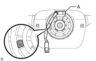
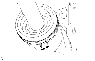
Check if the spiral cable sub-assembly is centered.
Text in Illustration 
Colored Part Tech Tips
When the spiral cable sub-assembly is centered, the part indicated by A is positioned at the top and the colored part shown in the illustration is visible.
-
If the spiral cable sub-assembly is not centered, center it.
Note
-
When rotating the spiral cable sub-assembly, make sure to push on the interlock indicated in the illustration to release the interlock mechanism.
-
Do not turn the spiral cable sub-assembly using the airbag wire harness.
-
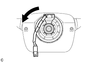
While pushing on the interlock indicated in the illustration, rotate the spiral cable sub-assembly counterclockwise slowly by hand until it stops.
Text in Illustration 
Interlock -
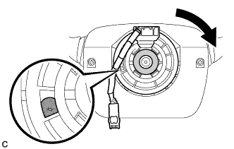
Rotate the spiral cable sub-assembly clockwise approximately 2.5 turns to the position where the colored part shown in the illustration is visible.
Text in Illustration Colored Part Interlock Tech Tips
The spiral cable sub-assembly will rotate approximately 2.5 turns to both the left and right from the center.
-
-
-
INSTALL STEERING WHEEL ASSEMBLY
-
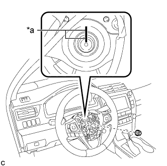
Text in Illustration *a Matchmark Install the steering wheel assembly aligning the matchmarks on the steering wheel assembly and steering main shaft.
-
Install the steering wheel assembly set nut.
- Torque:
- 50 N*m { 510 kgf*cm, 37 ft.*lbf }
-
Connect the connectors to the spiral cable sub-assembly.
-
-
INSPECT STEERING WHEEL CENTER POINT
-
INSTALL HORN BUTTON ASSEMBLY
-
INSTALL FRONT WHEEL LH
- Torque:
- 103 N*m { 1049 kgf*cm, 76 ft.*lbf }
-
CONNECT CABLE TO NEGATIVE BATTERY TERMINAL (for Power Tilt and Power Telescopic Steering Column)
Note
-
When disconnecting the cable, some systems need to be initialized after the cable is reconnected Click here.
-
Connect the cable to the negative (-) battery terminal with the front wheels facing straight ahead.
-
Reset the auto tilt away function setting to the previous condition by changing the customize parameter Click here.
-
-
TORQUE SENSOR ZERO POINT CALIBRATION
-
ADJUST PARKING ASSIST MONITOR SYSTEM