POWER TILT AND POWER TELESCOPIC STEERING COLUMN SYSTEM Tilt and Telescopic Manual Switch Circuit
DESCRIPTION
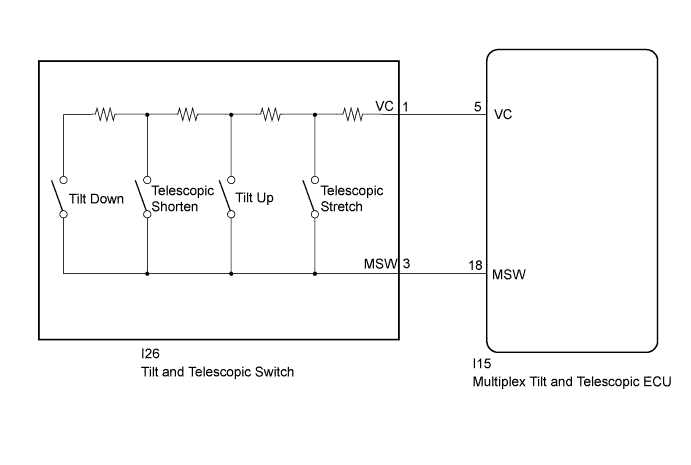
Different voltage values are sent to the multiplex tilt and telescopic ECU by operating the tilt and telescopic switch. The multiplex tilt and telescopic ECU then judges which motor and in which direction that motor should operate based on the voltage value.
WIRING DIAGRAM
INSPECTION PROCEDURE
PROCEDURE
-
READ VALUE USING INTELLIGENT TESTER (TILT UP/DOWN SWITCH, TELESCOPIC SHORT/LONG SWITCH)
-
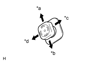
Text in Illustration *a Tilt Up *b Tilt Down *c Telescopic Extend (Long) *d Telescopic Contract (Short) Turn the engine switch off.
-
Connect the intelligent tester to the DLC3.
-
Turn the engine switch on (IG).
-
Turn the intelligent tester on.
-
Check the tilt and telescopic manual switch. Enter the following menus: Body / Tilt & Telescopic / Data List.
Tilt & Telescopic Tester Display Measurement Item/Range Normal Condition Diagnostic Note Telesco Short Switch Input state of telescopic contract switch/
OFF or ON
OFF: Telescopic contract switch not activated
ON: Telescopic contract switch activated
- Telesco Long Switch Input state of telescopic extend switch/
OFF or ON
OFF: Telescopic extend switch not activated
ON: Telescopic extend switch activated
- Tilt Down Switch Input state of tilt down switch/
OFF or ON
OFF: Tilt down switch not activated
ON: Tilt down switch activated
- Tilt Up Switch Input state of tilt up switch/
OFF or ON
OFF: Tilt up switch not activated
ON: Tilt up switch activated
- OK "ON" is displayed on the intelligent tester screen when each switch is turned on. "OFF" is displayed on the intelligent tester screen when each switch is turned off.
NG 
CHECK HARNESS AND CONNECTOR (ECU - TILT AND TELESCOPIC SWITCH) Click here
OK 
REPLACE MULTIPLEX TILT AND TELESCOPIC ECU Click here
-
-
CHECK HARNESS AND CONNECTOR (ECU - TILT AND TELESCOPIC SWITCH)
-
Disconnect the I15 multiplex tilt and telescopic ECU connector.
-
Disconnect the I26 tilt and telescopic switch connector.
-
Measure the resistance according to the value(s) in the table below.
Standard Resistance Tester Connection Condition Specified Condition I15-5 (VC) - I26-1 (VC) Always Below 1 Ω I15-18 (MSW) - I26-3 (MSW) I15-5 (VC) - Body ground 10 kΩ or higher I15-18 (MSW) - Body ground
NG 
REPAIR OR REPLACE HARNESS OR CONNECTOR
OK 
-
-
CHECK MULTIPLEX TILT AND TELESCOPIC ECU (VC TERMINAL VOLTAGE)
-
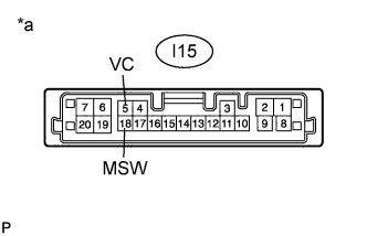
Text in Illustration *a Component with harness connected
(Multiplex Tilt and Telescopic ECU)
Reconnect the I15 multiplex tilt and telescopic ECU connector.
-
Measure the voltage according to the value(s) in the table below.
Standard Voltage Tester Connection Switch Condition Specified Condition I15-5 (VC) - I15-18 (MSW) Engine switch on (IG) 4.9 to 5.1 V
NG
REPLACE MULTIPLEX TILT AND TELESCOPIC ECU Click here
OK
-
-
CHECK TILT AND TELESCOPIC SWITCH
-
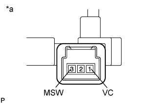
Text in Illustration *a Component without harness connected
(Tilt and Telescopic Switch)
Remove the tilt and telescopic switch Click here.
-
Measure the resistance according to the value(s) in the table below.
Standard Resistance Tester Connection Switch Condition Specified Condition 1(VC) - 3(MSW) Tilt up 342 to 378 Ω Tilt down 1890.5 to 2089.5 Ω Telescopic contract 750.5 to 829.5 Ω Telescopic extend 152 to 168 Ω
NG
REPLACE TILT AND TELESCOPIC SWITCH Click here
OK
PROCEED TO NEXT SUSPECTED AREA SHOWN IN PROBLEM SYMPTOMS TABLE Click here
-