STEERING COLUMN ASSEMBLY INSPECTION

Note
When using a vise, do not overtighten it.
-
INSPECT PRELOAD (for Manual Tilt and Manual Telescopic Steering Column)
-
Text in Illustration *1 Aluminum Plate *2 Wooden Block Secure the steering column assembly in a vice using aluminum plates as shown in the illustration.
Note
-
Do not overtighten the vice, as the steering column assembly may become deformed.
-
Support the steering column assembly with a wooden block or similar item to ensure that it does not fall.
-
-
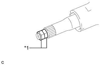
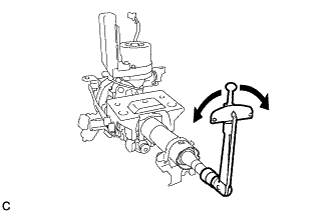
Text in Illustration *1 Service Nut Install the 2 service nuts to the steering main shaft.
Recommended service nut Thread diameter 12.0 mm (0.472 in.) Thread pitch 1.25 mm (0.0492 in.) -
Simultaneously rotate the service nut that was installed first counterclockwise and rotate the service nut that was installed second clockwise to lock them.
Note
Do not apply excess torque to the service nuts by using a tool such as an impact wrench.
Tech Tips
These nuts are installed to turn the steering main shaft. They should be removed after inspecting the steering main shaft rotating torque.
-
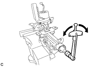
Using a torque wrench, turn the main shaft and measure the preload.
- Torque:
- Preload
- 1.0 to 1.8 N*m { 11 to 18 kgf*cm, 9 to 15 in.*lbf }
If the preload is not as specified, replace the power steering ECU with motor assembly or electric power steering column sub-assembly with a new one.
-
-
INSPECT PRELOAD (for Power Tilt and Power Telescopic Steering Column)
-
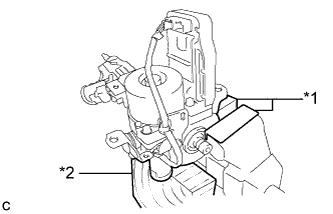
Text in Illustration *1 Wooden Block Securely set the steering column assembly on a wooden block or similar item.
Note
Be sure to hold the steering column assembly by hand so that it will not move while servicing.
-
Text in Illustration *1 Service Nut Install the 2 service nuts to the steering main shaft.
Recommended service nut Thread diameter 12.0 mm (0.472 in.) Thread pitch 1.25 mm (0.0492 in.) -
Simultaneously rotate the service nut that was installed first counterclockwise and rotate the service nut that was installed second clockwise to lock them.
Note
Do not apply excess torque to the service nuts by using a tool such as an impact wrench.
Tech Tips
These nuts are installed to turn the steering main shaft. They should be removed after inspecting the steering main shaft rotating torque.
-
Using a torque wrench, turn the main shaft and measure the preload.
- Torque:
- Preload
- 1.0 to 1.8 N*m { 11 to 18 kgf*cm, 9 to 15 in.*lbf }
If the preload is not as specified, replace the power steering ECU with motor assembly or electric power steering column sub-assembly with a new one.
-
-
INSPECT STEERING LOCK OPERATION (w/o Smart Entry and Start System)
-
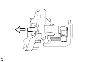
Check that the steering lock mechanism is activated when the key is removed.
-
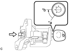
Text in Illustration *a LOCK *b ACC Check that the steering lock mechanism is deactivated when the key is inserted and turned to the ACC position.
If there is any abnormality, replace the ignition switch lock cylinder assembly or steering column upper bracket assembly with a new one.
-
-
INSPECT STEERING COLUMN ASSEMBLY
-
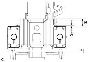
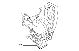
Text in Illustration *1 Capsule Check that the 2 capsules are securely installed to the steering column assembly as shown in the illustration.
Minimum Dimension A B 1 mm (0.0394 in.) 12 mm (0.473 in.) If the capsules are not positioned as specified, replace the electric power steering column sub-assembly with a new one.
-
Check the 2 capsules for deformation and damage.
If either of the capsules is deformed, loose, missing or damaged, replace the electric power steering column sub-assembly with a new one.
-
-
INSPECT TILT MOTOR
-
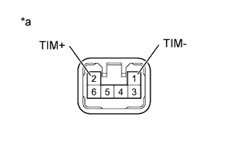
Text in Illustration *a Component without harness connected
(Tilt Motor)
Apply 12 V battery voltage to the tilt motor connector.
-
Then check the steering wheel tilt operation.
OK Measurement Condition Specified Condition
-
12 V battery positive (+) lead → Terminal 1 (TIM-)
-
12 V battery negative (-) lead → Terminal 2 (TIM+)
The steering wheel tilts down.
-
12 V battery positive (+) lead → Terminal 2 (TIM+)
-
12 V battery negative (-) lead → Terminal 1 (TIM-)
The steering wheel tilts up. -
-
-
INSPECT TELESCOPIC MOTOR
-
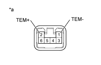
Text in Illustration *a Component without harness connected
(Telescopic Motor)
Apply 12 V battery voltage to the telescopic motor connector.
-
Then check the steering column telescopic operation.
OK Measurement Condition Specified Condition
-
12 V battery positive (+) lead → Terminal 2 (TEM+)
-
12 V battery negative (-) lead → Terminal 1 (TEM-)
The steering column contracts.
-
12 V battery positive (+) lead → Terminal 1 (TEM-)
-
12 V battery negative (-) lead → Terminal 2 (TEM+)
The steering column extends. -
-