PARKING BRAKE PEDAL (for LHD) INSTALLATION

-
INSTALL PARKING BRAKE CONTROL PEDAL ASSEMBLY
-
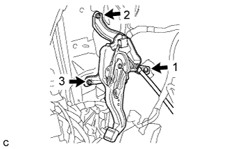
Install the parking brake control pedal assembly with the bolt and 2 nuts.
- Torque:
- 15 N*m { 153 kgf*cm, 11 ft.*lbf }
Note
Tighten the bolt and 2 nuts in the order shown in the illustration.
-
Connect the parking brake switch connector.
-
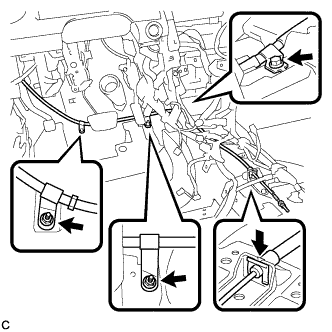
Install the No. 1 parking brake cable assembly with the bolt and 2 nuts.
- Torque:
- Bolt
- 15 N*m { 153 kgf*cm, 11 ft.*lbf }
- Nut
- 5.4 N*m { 55 kgf*cm, 48 in.*lbf }
-
Install the clip to the No. 1 parking brake cable assembly.
-
Install the floor carpet.
-
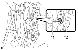
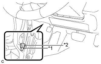
Text in Illustration *1 Lock Nut *2 Adjusting Nut Temporarily install the lock nut.
Tech Tips
After adjusting parking brake pedal travel, tighten the lock nut.
-
-
CONNECT NO. 4 PARKING BRAKE CABLE ASSEMBLY
-
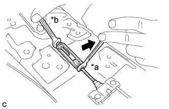
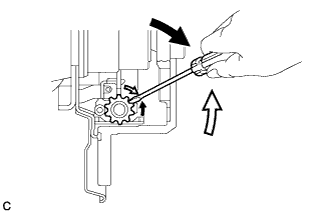
Text in Illustration *a Turn *b Hold Connect the No. 4 parking brake cable assembly to the parking brake control pedal assembly as shown in the illustration.
- Torque:
- 5.4 N*m { 55 kgf*cm, 48 in.*lbf }
-
-
INSTALL AIRBAG SENSOR ASSEMBLY
-
Check that the ignition switch is off.
-
Check that the cable is disconnected from the negative (-) battery terminal.
CAUTION:
Wait at least 90 seconds after disconnecting the cable from the negative (-) battery terminal to disable the SRS system.
-
Using SST, install the airbag sensor assembly with the 3 bolts.
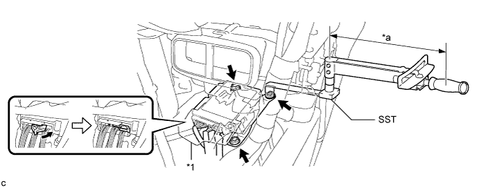
- SST
- 09961-00950
Text in Illustration *1 Waterproof Sheet - - *a Fulcrum Length - - - Torque:
- without SST
- 18 N*m { 178 kgf*cm, 13 ft.*lbf }
- with SST
- 11 N*m { 112 kgf*cm, 8 ft.*lbf }
Note
-
Use a torque wrench with a fulcrum length of 250 mm (9.84 in.).
-
This torque value is effective when SST is parallel to a torque wrench.
-
If the airbag sensor assembly has been dropped, or there are any cracks, dents or other defects in the case or connector, replace it with a new one.
-
When installing the airbag sensor assembly, be careful that the SRS wiring does not interfere with or is not pinched between other parts.
-
When the ignition switch is first turned to ON after the airbag sensor assembly has been replaced, make sure that no one is in the vehicle.
-
Connect the connectors to the airbag sensor assembly as shown in the illustration.
Note
When connecting any airbag connector, take care not to damage the airbag wire harness.
-
Check that the waterproof sheet is properly set.
-
Check that there is no looseness in the installation parts of the airbag sensor assembly.
-
-
INSTALL FLOOR CARPET BRACKET RH
-
Engage the 2 guides.
-
Install the floor carpet bracket RH with the 2 clips.
-
-
INSTALL NO. 1 INDOOR ELECTRICAL KEY ANTENNA ASSEMBLY (for Built-in Type Yaw Rate Sensor)
w/ Smart Entry and Start System: Click here
-
INSTALL YAW RATE SENSOR BRACKET (for Separate Type Yaw Rate Sensor)
-
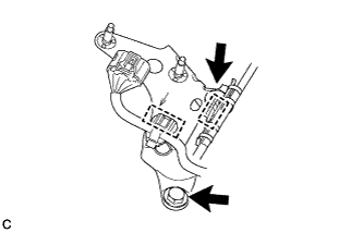
Install the yaw rate sensor bracket with the 2 bolts.
- Torque:
- 13 N*m { 127 kgf*cm, 9 ft.*lbf }
-
Engage the 2 clamps to install the wire harnesses.
-
-
INSTALL NO. 3 INDOOR ELECTRICAL KEY ANTENNA ASSEMBLY (for Separate Type Yaw Rate Sensor)
w/ Smart Entry and Start System: Click here
-
INSTALL YAW RATE SENSOR (for Separate Type Yaw Rate Sensor)
-
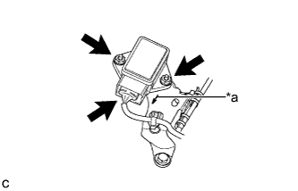
Text in Illustration *a Arrow Mark Install the yaw rate sensor to the yaw rate sensor bracket with the 2 nuts.
- Torque:
- 6.5 N*m { 66 kgf*cm, 58 in.*lbf }
Note
-
Do not damage the yaw sensor.
-
Make sure that the yaw rate sensor is installed securely.
-
Do not use dropped or damaged parts.
-
Keep the contact surfaces of the yaw rate sensor and yaw rate sensor bracket free of foreign matter.
-
Make sure that the connector end of the yaw rate sensor is facing in the same direction as the arrow mark on the bracket when installing the yaw rate sensor.
-
Connect the connector to the yaw rate sensor.
Note
Make sure that the yaw rate sensor connector is connected securely.
-
-
INSTALL LOWER NO. 1 INSTRUMENT PANEL AIRBAG ASSEMBLY (w/ Driver Side Knee Airbag)
-
Check that the ignition switch is off.
-
Check that the cable is disconnected from the negative (-) battery terminal.
CAUTION:
Wait at least 90 seconds after disconnecting the cable from the negative (-) battery terminal to disable the SRS system.
-
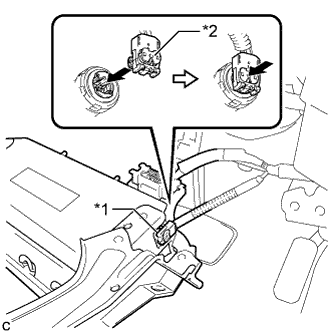
Text in Illustration *1 Airbag Connector *2 Airbag Connector Lock Connect the airbag connector to the lower No. 1 instrument panel airbag assembly.
Note
When connecting any airbag connector, take care not to damage the airbag wire harness.
-
Push in the lock to install the airbag connector.
-
Temporarily install the lower No. 1 instrument panel airbag assembly with the 2 hooks.
-
Engage the 2 claws to install the DLC3.
-
Install the 4 bolts.
- Torque:
- 10 N*m { 102 kgf*cm, 7 ft.*lbf }
Note
Confirm that the lower No. 1 instrument panel airbag assembly is installed securely without any excessive gaps and is not protruding outward.
-
-
INSTALL SHIFT LEVER SUPPORT
-
for U660E Click here
-
for U760E Click here
-
-
CONNECT CABLE TO NEGATIVE BATTERY TERMINAL
Note
When disconnecting the cable, some systems need to be initialized after the cable is reconnected Click here.
-
PERFORM DIAGNOSTIC SYSTEM CHECK
for Separate Type Yaw Rate Sensor: Click here
for Built-in Type Yaw Rate Sensor: Click here
-
INSPECT SRS WARNING LIGHT
for Separate Type Yaw Rate Sensor: Click here
for Built-in Type Yaw Rate Sensor: Click here
-
ADJUST PARKING BRAKE PEDAL TRAVEL
-
Completely release the parking brake pedal.
-
Text in Illustration *1 Lock Nut *2 Adjusting Nut Loosen the lock nut and the adjusting nut to completely release the parking brake cable.
-
Remove the rear wheels.
-
Temporarily install the hub nuts to the hub bolts.
Tech Tips
Securely install the hub nuts to the rear disc.
-
Remove the parking brake shoe adjusting hole plug.
-
Turn the shoe adjuster and expand the shoes until the disc locks.
Text in Illustration 
Expand 
Contract -
Turn and contract the shoe adjuster until the disc can rotate smoothly.
Standard Returns 8 notches. -
Check that there is no brake drag against the shoes.
-
Install the parking brake shoe adjusting hole plug.
-
Turn the adjusting nut until the parking brake pedal travel is corrected to be within the specified range.
Parking brake pedal travel 7 to 10 notches at 300 N (31 kgf, 67.5 lbf) -
Using a wrench or an equivalent tool, hold the adjusting nut and tighten the lock nut.
- Torque:
- 9.0 N*m { 92 kgf*cm, 80 in.*lbf }
-
Operate the parking brake pedal 3 to 4 times, and check the parking brake pedal travel.
-
Check that the parking brake does not drag.
-
Remove the hub nuts from the hub bolts.
-
Install the rear wheels.
- Torque:
- 103 N*m { 1049 kgf*cm, 76 ft.*lbf }
-
-
INSPECT BRAKE WARNING LIGHT
-
When operating the parking brake pedal, check that the brake warning light illuminates.
Standard The brake warning light always illuminates at the first click.
-