BRAKE BOOSTER (for RHD) REMOVAL

Note
Make sure to release vacuum from the brake booster assembly before removing the brake master cylinder sub-assembly from the brake booster assembly.
-
PRECAUTION
Note
After turning the ignition switch off, waiting time may be required before disconnecting the cable from the negative (-) battery terminal, Therefore, make sure to read the disconnecting the cable from the negative (-) battery terminal notices before proceeding with work Click here.
-
RECOVER REFRIGERANT FROM AIR CONDITIONING SYSTEM
-
Turn the A/C switch on.
-
Operate the air conditioning with a set temperature of 25°C (77°F) and the blower at low for 10 minutes to circulate the refrigerant. This causes most of the compressor oil from the various components of the air conditioning system to collect in the air conditioning compressor.
-
Turn the ignition switch off.
-
Recover the refrigerant from the air conditioning system using a refrigerant recovery unit.
-
-
DISCONNECT CABLE FROM NEGATIVE BATTERY TERMINAL
Note
When disconnecting the cable, some systems need to be initialized after the cable is reconnected Click here.
-
REMOVE BRAKE MASTER CYLINDER SUB-ASSEMBLY
-
REMOVE FRONT BUMPER COVER
-
REMOVE RADIATOR SIDE DEFLECTOR RH
-
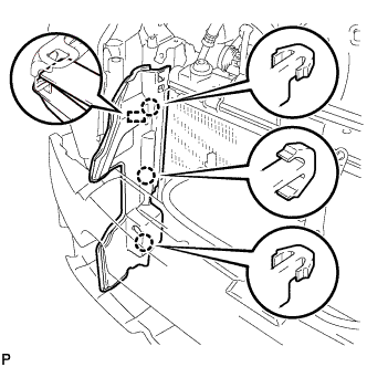
Disengage the 3 claws and guide remove the radiator side deflector RH.
-
-
SEPARATE AIR CONDITIONING TUBE AND ACCESSORY ASSEMBLY
-
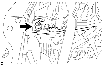
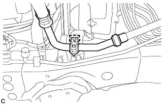
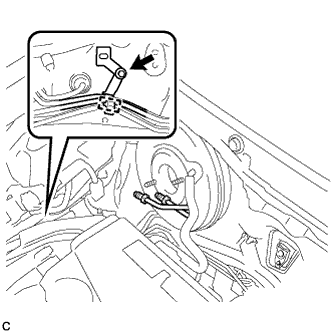
Disconnect the pressure sensor connector and separate the clamp.
-
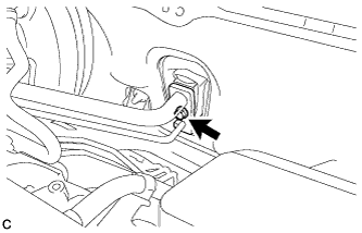
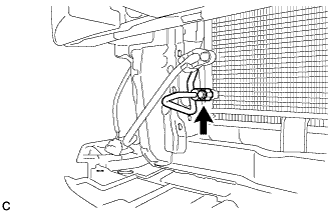
Remove the bolt from the hook connector.
-
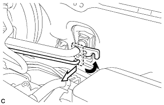
Turn the hook connector and separate the air conditioning tube and accessory assembly from the air conditioning unit.
Note
-
Do not deform the piping.
-
Do not damage the plastic clamp.
-
-
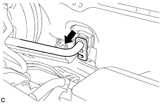
Remove the bolt and separate the air conditioning tube and accessory assembly from the cooler condenser assembly.
Note
-
Do not deform the piping.
-
Do not damage the plastic clamp.
-
-
Remove the 2 O-rings from the air conditioning tube and accessory assembly.
Note
Seal the openings of the disconnected parts using vinyl tape to prevent entry of moisture and foreign matter.
-
-
SEPARATE SUCTION PIPE SUB-ASSEMBLY
-
Disengage the clamp from the brake actuator bracket assembly.
-
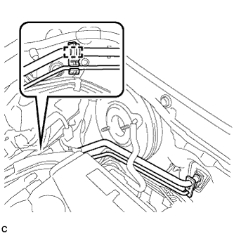
Separate the clamp with suction pipe sub-assembly and air conditioning tube and accessory assembly from the No. 1 brake tube clamp.
-
Separate the suction pipe sub-assembly from the air conditioning unit.
Note
-
Do not deform the piping.
-
Do not damage the plastic clamp.
-
-
Remove the O-ring from the suction pipe sub-assembly.
Note
Seal the openings of the disconnected parts using vinyl tape to prevent entry of moisture and foreign matter.
-
-
REMOVE NO. 1 BRAKE TUBE CLAMP
-
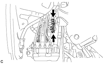
Disengage the clamp from the brake lines.
Note
Do not kink or damage the brake lines.
-
Remove the bolt and No. 1 brake tube clamp from the vehicle body.
-
-
REMOVE BRAKE LINE
-
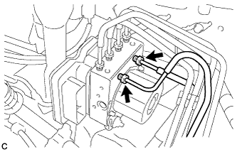
Using a union nut wrench, disconnect the 2 brake lines from the brake actuator assembly.
-
Remove the 2 clamps to make the 2 brake lines free.
Note
-
Do not kink or damage the brake lines.
-
Do not allow any foreign matter such as dirt and dust to enter the brake lines.
-
-
-
REMOVE VACUUM SWITCHING VALVE ASSEMBLY
-
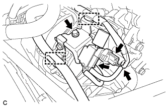
Disconnect the union to check valve hose and wire harness clamp.
-
Disconnect the 2 vacuum hoses and connector.
-
Remove the bolt and vacuum switching valve assembly.
-
-
DISCONNECT UNION TO CHECK VALVE HOSE
-
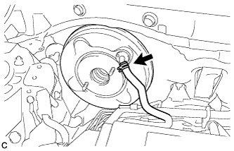
Slide the clip and disconnect the union to check valve hose from the brake booster assembly.
-
-
REMOVE PUSH ROD PIN
-
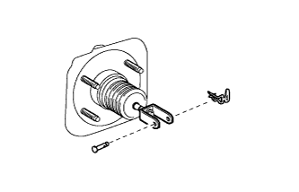
Remove the clip and push rod pin.
-
Separate the brake master cylinder push rod clevis from the brake pedal support assembly.
-
-
REMOVE BRAKE BOOSTER ASSEMBLY
-
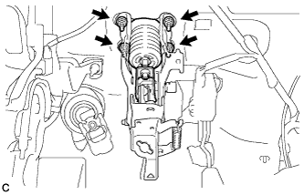
Remove the 4 nuts and brake booster assembly from the vehicle body.
Note
Do not kink or damage the brake lines, air conditioning tube and accessory assembly or suction pipe sub-assembly.
-
-
REMOVE BRAKE BOOSTER GASKET
-
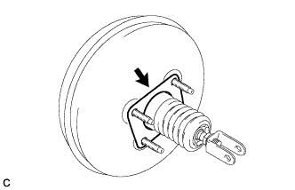
Remove the brake booster gasket from the brake booster assembly.
-
-
REMOVE BRAKE MASTER CYLINDER PUSH ROD CLEVIS
-
Loosen the lock nut and remove the brake master cylinder push rod clevis and lock nut.
-
-
REMOVE BRAKE VACUUM CHECK VALVE ASSEMBLY
-
Remove the brake vacuum check valve assembly from the brake booster assembly.
-
-
REMOVE CHECK VALVE GROMMET
-
Remove the check valve grommet from the brake booster assembly.
-