VEHICLE STABILITY CONTROL SYSTEM, Diagnostic DTC:C1381

| DTC Code | DTC Name |
|---|---|
| C1381 | Acceleration Sensor Power Supply Voltage Malfunction |
DESCRIPTION
This DTC is stored when the skid control ECU receives a sensor supply voltage malfunction signal from the yaw rate and acceleration sensor (for separate type) or yaw rate and acceleration sensor (airbag sensor assembly) (for built-in type).
| DTC No. | DTC Detection Condition | Trouble Area |
|---|---|---|
| C1381 | Vehicle speed is 6 km/h (4 mph) and yaw rate and acceleration sensor power supply malfunction signal is received for 1.1 seconds or more. |
|
WIRING DIAGRAM
Refer to DTCs C1234 and C1472 Click here.
INSPECTION PROCEDURE
PROCEDURE
-
CONFIRM YAW RATE AND ACCELERATION SENSOR TYPE
-
Confirm the yaw rate and acceleration sensor type.
Result Result Proceed to Yaw rate and acceleration sensor (for separate type) A Yaw rate and acceleration sensor (airbag sensor assembly) (for built-in type) B
B 
CHECK HARNESS AND CONNECTOR (POWER SOURCE TERMINAL) Click here
A 
-
-
CHECK HARNESS AND CONNECTOR (POWER SOURCE TERMINAL)
-
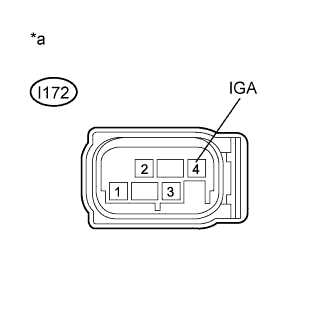
Text in Illustration *a Front view of wire harness connector
(to Yaw Rate and Acceleration Sensor)
Make sure that there is no looseness at the locking part and the connecting part of the connector.
-
Disconnect the yaw rate and acceleration sensor connector.
-
Turn the ignition switch to ON.
-
Measure the voltage according to the value(s) in the table below.
Standard Voltage Tester Connection Condition Specified Condition I172-4 (IGA) - Body ground Ignition switch ON 11 to 14 V
NG 
REPAIR OR REPLACE HARNESS OR CONNECTOR (POWER SOURCE CIRCUIT)
OK
-
-
CHECK HARNESS AND CONNECTOR (GROUND TERMINAL)
-
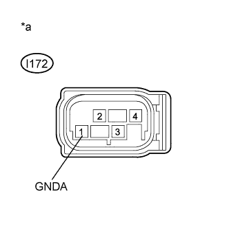
Text in Illustration *a Front view of wire harness connector
(to Yaw Rate and Acceleration Sensor)
Turn the ignition switch off.
-
Measure the resistance according to the value(s) in the table below.
Standard Resistance Tester Connection Condition Specified Condition I172-1 (GNDA) - Body ground Always Below 1 Ω Tech Tips
If troubleshooting has been carried out according to Problem Symptoms Table, refer back to the table and proceed to the next step before replacing parts Click here.
NG
REPAIR OR REPLACE HARNESS OR CONNECTOR (GROUND CIRCUIT)
OK 
REPLACE YAW RATE AND ACCELERATION SENSOR Click here
-
-
CHECK HARNESS AND CONNECTOR (POWER SOURCE TERMINAL)
-
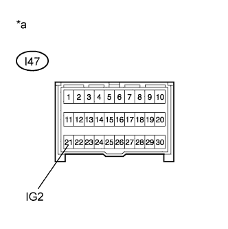
Text in Illustration *a Front view of wire harness connector
(to Yaw Rate and Acceleration Sensor (Airbag Sensor Assembly))
Make sure that there is no looseness at the locking part and the connecting part of the connector.
-
Disconnect the yaw rate and acceleration sensor (airbag sensor assembly) connector.
-
Turn the ignition switch to ON.
-
Measure the voltage according to the value(s) in the table below.
Standard Voltage Tester Connection Condition Specified Condition I47-21 (IG2) - Body ground Ignition switch ON 11 to 14 V
NG
REPAIR OR REPLACE HARNESS OR CONNECTOR (POWER SOURCE CIRCUIT)
OK
-
-
CHECK HARNESS AND CONNECTOR (GROUND TERMINAL)
-
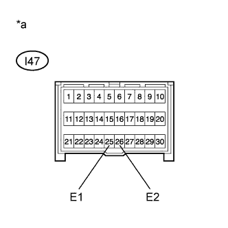
Text in Illustration *a Front view of wire harness connector
(to Yaw Rate and Acceleration Sensor (Airbag Sensor Assembly))
Turn the ignition switch off.
-
Measure the resistance according to the value(s) in the table below.
Standard Resistance Tester Connection Condition Specified Condition I47-25 (E1) - Body ground Always Below 1 Ω I47-26 (E2) - Body ground Always Below 1 Ω Tech Tips
If troubleshooting has been carried out according to Problem Symptoms Table, refer back to the table and proceed to the next step before replacing parts Click here.
NG
REPAIR OR REPLACE HARNESS OR CONNECTOR (GROUND CIRCUIT)
OK
REPLACE AIRBAG SENSOR ASSEMBLY Click here
-