REAR LOWER ARM INSTALLATION

Tech Tips
The rear No. 2 suspension arm assembly RH can be installed directly to the vehicle.
-
INSTALL REAR NO. 1 SUSPENSION ARM ASSEMBLY LH
-
Temporarily tighten the rear No. 1 suspension arm assembly LH (inner side) with the bolt.
Text in Illustration 
Bolt 
Front of the Vehicle 
Paint Mark Tech Tips
Ensure that the paint mark faces the rear of the vehicle.
-
Set the rear No.1 suspension arm assembly in the position shown in the illustration, and fully tighten the bolt.
- Torque:
- 100 N*m { 1020 kgf*cm, 74 ft.*lbf }
-
-
INSTALL REAR NO. 1 SUSPENSION ARM ASSEMBLY RH
Tech Tips
Perform the same procedure as for the LH side.
-
TEMPORARILY TIGHTEN REAR NO. 2 SUSPENSION ARM ASSEMBLY LH
-
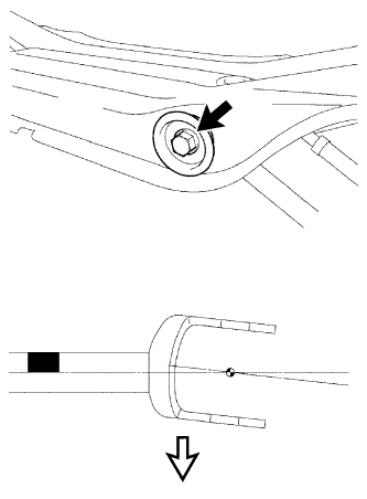
Temporarily tighten the rear No. 2 suspension arm assembly LH (inside) with the bolt.
Text in Illustration Bolt Paint Mark Tech Tips
Ensure that the paint mark faces the rear of the vehicle.
-
-
INSTALL REAR SUSPENSION MEMBER SUB-ASSEMBLY
-
TEMPORARILY TIGHTEN REAR NO. 2 SUSPENSION ARM ASSEMBLY RH
-
Temporarily tighten the rear No. 2 suspension arm assembly RH (inside) with the bolt.
Text in Illustration Bolt Paint Mark Tech Tips
Ensure that the paint mark faces the rear of the vehicle.
-
-
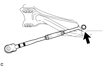
CONNECT REAR NO. 2 SUSPENSION ARM ASSEMBLY RH
-
Connect the rear No. 2 suspension arm assembly RH (outer side) to the rear axle carrier sub-assembly with the bolt and nut.
Note
When temporarily tightening the bolt, keep the nut from rotating.
Tech Tips
Insert the bolt from the rear of the vehicle.
-
-
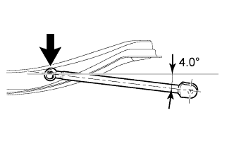
STABILIZE SUSPENSION
-
Text in Illustration *1 Wooden Block Jack up the rear axle carrier sub-assembly, placing a wooden block under it to avoid damage. Apply load to the suspension so that the installed bolt of the rear No. 1 suspension arm assembly (inner side) is horizontally aligned with the center of the rear axle hub.
CAUTION:
Do not jack up the rear axle carrier sub-assembly too high as the vehicle may fall.
Note
-
When jacking up the rear axle carrier sub-assembly, be sure to jack it up slowly.
-
Make sure to perform this operation with the vehicle kept as low as possible.
-
-
-
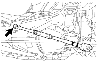
FULLY TIGHTEN REAR NO. 2 SUSPENSION ARM ASSEMBLY RH
-
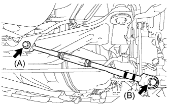
Fully tighten the bolt (A).
- Torque:
- 100 N*m { 1020 kgf*cm, 74 ft.*lbf }
-
Fully tighten the bolt (B).
- Torque:
- 100 N*m { 1020 kgf*cm, 74 ft.*lbf }
Note
When fully tightening the bolt, keep the nut from rotating.
-
-
INSTALL REAR HEIGHT CONTROL SENSOR SUB-ASSEMBLY (w/ Height Control Sensor)
-
INSTALL REAR WHEELS
- Torque:
- 103 N*m { 1049 kgf*cm, 76 ft.*lbf }
-
INSPECT AND ADJUST REAR WHEEL ALIGNMENT
-
INITIALIZE HEIGHT CONTROL SENSOR SIGNAL (w/ Height Control Sensor)
-
for AFS (Adaptive Front-Lighting System) : Click here
-
for Automatic Headlight Beam Level Control System: Click here
-
-
ADJUST HEADLIGHT AIMING (w/ Height Control Sensor)