FRONT DRIVE SHAFT ASSEMBLY (for 2AR-FE) REASSEMBLY

-
INSTALL FRONT DRIVE SHAFT BEARING (for RH Side)
-
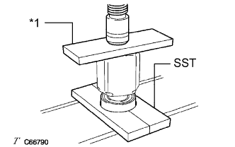
Text in Illustration *1 Steel Plate Using SST, a steel plate and a press, install a new front drive shaft bearing.
- SST
- 09527-10011
Note
The bearing should be completely installed.
-
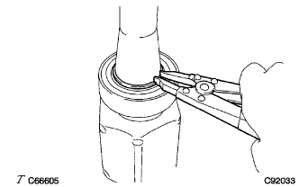
Using a snap ring expander, install a new drive shaft hole snap ring.
-
-
INSTALL FRONT DRIVE SHAFT DUST COVER (for RH Side)
-
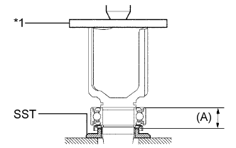
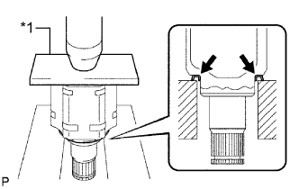
Text in Illustration *1 Steel Plate Using SST, a steel plate and a press, install a new front drive shaft dust cover.
- SST
- 09726-40010
Dimension (A) 26.6 to 27.6 mm (1.05 to 1.08 in.) Note
-
The dust cover should be completely installed.
-
Be careful not to damage the front drive shaft dust cover.
-
-
INSTALL FRONT DRIVE SHAFT DUST COVER RH
-
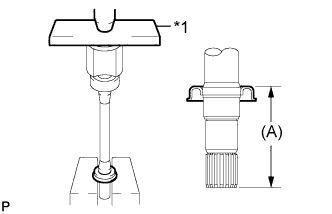
Text in Illustration *1 Steel Plate Using a steel plate and a press, install a new front drive shaft dust cover RH until dimension (A) from the tip of the front drive inboard joint assembly to the front drive shaft dust cover RH meets the specification.
Dimension (A) 110.0 to 111.0 mm (4.33 to 4.37 in.) Note
-
The dust cover should be completely installed.
-
Be careful not to damage the front drive shaft dust cover RH.
-
-
-
INSTALL FRONT DRIVE SHAFT DUST COVER LH
-
Text in Illustration *1 Steel Plate Using a steel plate and a press, install a new front drive shaft dust cover LH.
Note
-
The dust cover should be completely installed.
-
Be careful not to damage the front drive shaft dust cover LH.
-
-
-
INSTALL FRONT AXLE OUTBOARD JOINT BOOT
-
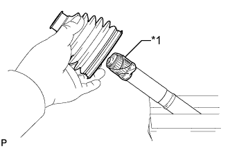
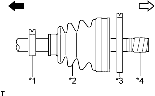
Text in Illustration *1 Protective Tape Wrap the splines of the front drive outboard joint shaft assembly with protective tape to prevent the boot from being damaged.
-
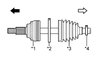
Text in Illustration *1 Front Drive Outboard Joint Shaft Assembly *2 Front No. 2 Axle Outboard Joint Boot Clamp *3 Front Axle Outboard Joint Boot *4 Front Axle Outboard Joint Boot Clamp 
Outboard Joint Side 
Inboard Joint Side Install new parts onto the front drive outboard joint shaft assembly in the following order:
-
Front No. 2 axle outboard joint boot clamp
-
Front axle outboard joint boot
-
Front axle outboard joint boot clamp
-
-
Pack the joint portion of the front drive outboard joint shaft assembly and front axle outboard joint boot with grease.
Standard grease capacity (for TMC Made) 171 to 181 g (6.0 to 6.3 oz.) Standard grease capacity (except TMC Made) 100 to 120 g (3.5 to 4.2 oz.) -
Install the front axle outboard joint boot onto the front drive outboard joint shaft assembly groove.
Note
-
Do not allow grease to adhere to the boot clamp track of the outboard joint boot.
-
Keep the inside of the outboard joint boot free of foreign matter.
-
-
-
INSTALL FRONT NO. 2 AXLE OUTBOARD JOINT BOOT CLAMP (for TMC Made)
CAUTION:
Wear protective gloves. Sharp areas on the parts may injure your hands.
-
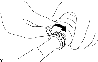
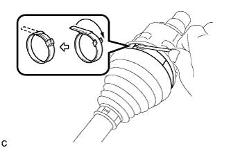
Install the front No. 2 axle outboard joint boot clamp onto the front axle outboard joint boot and temporarily fold back the lever.
Note
-
Set the lever into the guide groove correctly and install the clamp as far into the inside of the vehicle as possible.
-
Check the band and the lever for any deformation before folding back the lever.
-
-
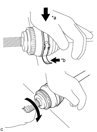
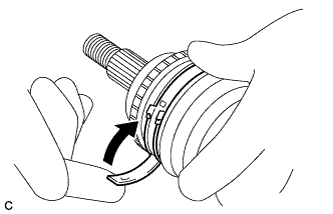
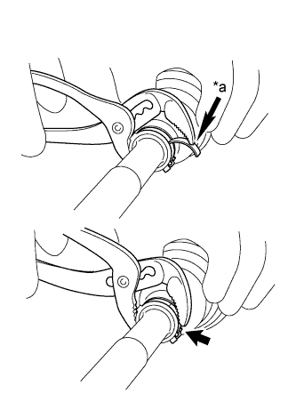
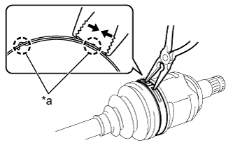
Text in Illustration *a Weight *b Contact Lean your weight on your hand and roll the outboard joint forward while pressing the outboard joint against the work surface. Roll the outboard joint and fold the lever until a click sound can be heard.
Note
-
Do not damage the speed sensor rotor.
-
Make sure that the outboard joint is in direct contact with the work surface.
-
-
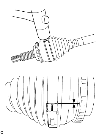
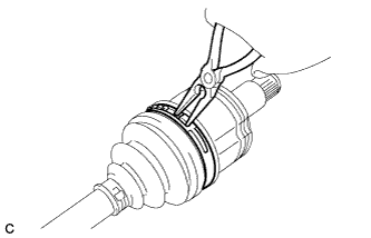
Using a plastic hammer, tap the buckle to secure it while adjusting the clearance between the lever and the groove to make the clearance between the buckle edge and the lever end even.
Note
-
Do not use too much force when tapping with the plastic hammer.
-
Do not damage the front axle outboard joint boot.
-
-
-
INSTALL FRONT NO. 2 AXLE OUTBOARD JOINT BOOT CLAMP (except TMC Made)
-
Hold the drive shaft in a vise between aluminum plates.
Note
Do not overtighten the vise.
-
Install the front No. 2 axle outboard joint boot clamp onto the front axle outboard joint boot.
-
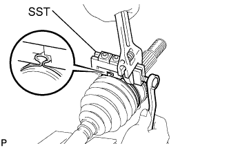
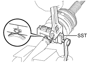
Place SST onto the front No. 2 axle outboard joint boot clamp, press it against the boot and slightly tighten SST.
- SST
- 09521-24010
-
Tighten SST so that the front No. 2 axle outboard joint boot clamp is pinched.
Note
Do not overtighten SST.
-
Remove SST.
-
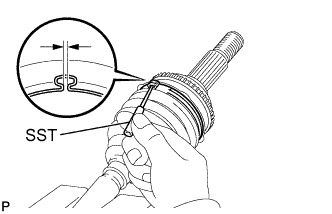
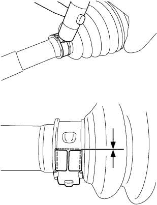
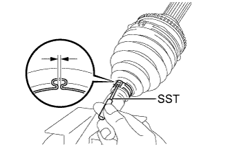
Using SST, measure the clearance of the front No. 2 axle outboard joint boot clamp.
- SST
- 09240-00020
Clearance 1.2 to 4.0 mm (0.0472 to 0.157 in.) If the clearance is outside the specified range, retighten SST.
-
-
INSTALL FRONT AXLE OUTBOARD JOINT BOOT CLAMP (for TMC Made)
CAUTION:
Wear protective gloves. Sharp areas on the parts may injure your hands.
-
Install the front axle outboard joint boot clamp onto the front axle outboard joint boot and temporarily fold back the lever.
Note
-
Set the lever into the guide groove correctly.
-
Check the band and the lever for any deformation before folding back the lever.
-
-
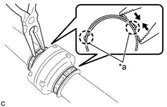
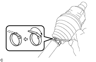
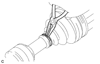
Text in Illustration *a Place the tip near the center of the lever. Using water pump pliers, pinch the front axle outboard joint boot clamp to temporarily secure it.
-
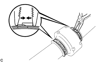
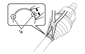
Using a plastic hammer, tap the buckle to secure it while adjusting the clearance between the lever and the groove to make the clearance between the buckle edge and the lever end even.
Note
Do not damage the front axle outboard joint boot.
-
-
INSTALL FRONT AXLE OUTBOARD JOINT BOOT CLAMP (except TMC Made)
-
Install the front axle outboard joint boot clamp onto the front axle outboard joint boot.
-
Place SST onto the front axle outboard joint boot clamp, press it against the boot and slightly tighten SST.
- SST
- 09521-24010
-
Tighten SST so that the front axle outboard joint boot clamp is pinched.
Note
Do not overtighten SST.
-
Remove SST.
-
Using SST, measure the clearance of the front axle outboard joint boot clamp.
- SST
- 09240-00020
Clearance 1.2 to 4.0 mm (0.0472 to 0.157 in.) If the clearance is outside the specified range, retighten SST.
-
-
INSTALL FRONT DRIVE SHAFT DAMPER (w/ 1 Clamp)
-
Install a new front drive shaft damper clamp onto the front drive outboard joint shaft assembly.
-
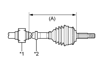
Text in Illustration *1 Front Drive Shaft Damper *2 Front Drive Shaft Damper Clamp Install the front drive shaft damper onto the front drive outboard joint shaft assembly.
-
Set the dimension as specified below.
Dimension (A) 223.4 to 227.4 mm (8.80 to 8.95 in.) -
Install the front drive shaft damper clamp onto the front drive shaft damper.
Note
Be sure to install the clamp in the correct position.
-
Hold the drive shaft in a vise between aluminum plates.
Note
Do not overtighten the vise.
-
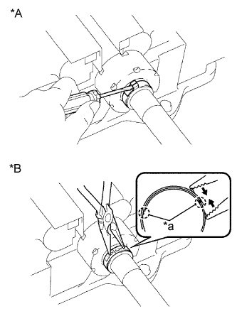
Text in Illustration *A for One Touch Type *B for Claw Engagement Type for TMC Made One Touch Type:
-
Using a screwdriver, install the front drive shaft damper clamp.
-
-
for TMC Made Claw Engagement Type:
-
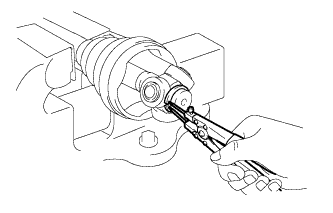
Using needle nose pliers, install the front drive shaft damper clamp.
-
-
except TMC Made:
-
Text in Illustration *a Claws Using needle nose pliers, install the front drive shaft damper clamp.
-
-
-
INSTALL FRONT DRIVE SHAFT DAMPER (w/ 2 Clamps)
-
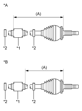
Text in Illustration *A for TMC Made *B except TMC Made *1 Front Drive Shaft Damper *2 Front Drive Shaft Damper Clamp Temporarily install the front drive shaft damper and 2 new front drive shaft damper clamps to the front drive outboard joint shaft assembly as shown in the illustration.
-
Set the dimension as specified below.
Dimension (A) for TMC Made LH 277.9 to 281.9 mm (10.9 to 11.1 in.) RH 261.4 to 265.4 mm (10.3 to 10.4 in.) except TMC Made LH 223.4 to 227.4 mm (8.80 to 8.95 in.) RH 223.8 to 227.8 mm (8.81 to 8.97 in.) -
Install the 2 front drive shaft damper clamps onto the front drive shaft damper.
Note
Be sure to install the clamp in the correct position.
-
Hold the drive shaft in a vise between aluminum plates.
Note
Do not overtighten the vise.
-
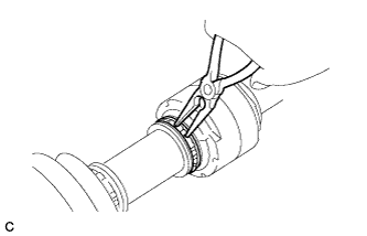
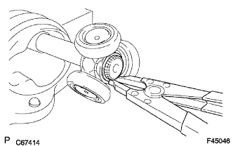
Text in Illustration *a Claws for TMC Made:
-
Using needle nose pliers, install the 2 front drive shaft damper clamps.
-
-
except TMC Made:
-
Using needle nose pliers, install the 2 front drive shaft damper clamps.
-
-
-
INSTALL FRONT DRIVE INBOARD JOINT ASSEMBLY (for TMC Made)
-
Text in Illustration *1 Front Axle Inboard Joint Boot Clamp *2 Front Axle Inboard Joint Boot *3 Front No. 2 Axle Inboard Joint Boot Clamp *4 Protective Tape Outboard Joint Side Inboard Joint Side Install new parts onto the front drive outboard joint shaft assembly in the following order:
-
Front axle inboard joint boot clamp
-
Front axle inboard joint boot
-
Front No. 2 axle inboard joint boot clamp
-
-
Hold the drive shaft in a vise between aluminum plates.
Note
Do not overtighten the vise.
-
Remove the protective tape.
-
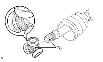
Text in Illustration *a Matchmark Align the matchmarks and install the tripod joint onto the front drive outboard joint shaft assembly.
-
Align the matchmarks placed before removal.
-
Using a brass bar and a hammer, install the tripod joint to the front drive outboard joint shaft assembly.
Note
-
Do not tap the rollers.
-
Keep the tripod joint free of foreign matter.
-
-
Using a snap ring expander, install a new shaft snap ring to the front drive outboard joint shaft assembly.
-
Pack the front drive inboard joint assembly and front axle inboard boot with grease.
Standard grease capacity 175 to 185 g (6.2 to 6.5 oz.) -
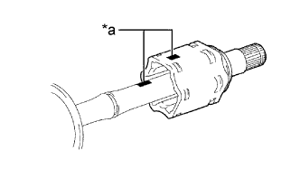
Text in Illustration *a Matchmark Align the matchmarks and install the front drive inboard joint assembly to the front drive outboard joint shaft assembly.
-
-
INSTALL FRONT DRIVE INBOARD JOINT ASSEMBLY (except TMC Made)
-
Text in Illustration *1 Front Axle Inboard Joint Boot Clamp *2 Front Axle Inboard Joint Boot *3 Front No. 2 Axle Inboard Joint Boot Clamp *4 Protective Tape Outboard Joint Side Inboard Joint Side Install new parts onto the front drive outboard joint shaft assembly in the following order:
-
Front axle inboard joint boot clamp
-
Front axle inboard joint boot
-
Front No. 2 axle inboard joint boot clamp
-
-
Hold the drive shaft in a vise between aluminum plates.
Note
Do not overtighten the vise.
-
Remove the protective tape.
-
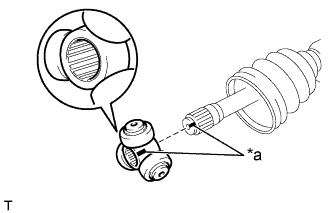
Text in Illustration *a Matchmark Align the matchmarks and install the tripod joint onto the front drive outboard joint shaft assembly.
-
Align the matchmarks placed before removal.
-
Using a brass bar and a hammer, install the tripod joint to the front drive outboard joint shaft assembly.
Note
-
Do not tap the rollers.
-
Keep the tripod joint free of foreign matter.
-
-
Using a snap ring expander, install a new shaft snap ring to the front drive outboard joint shaft assembly.
-
Pack the front drive inboard joint assembly and front axle inboard boot with grease.
Standard grease capacity (LH Side) 150 to 170 g (5.3 to 5.9 oz.) Standard grease capacity (RH Side) 155 to 175 g (5.5 to 6.1 oz.) -
Text in Illustration *a Matchmark Align the matchmarks and install the front drive inboard joint assembly to the front drive outboard joint shaft assembly.
-
-
INSTALL FRONT AXLE INBOARD JOINT BOOT
-
Install the front axle inboard joint boot to the front drive inboard joint assembly.
-
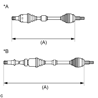
Text in Illustration *A LH Side *B RH Side Check whether the drive shaft dimensions (A) are within the following specifications.
Dimension (A) for TMC Made except TMC Made LH Side 585.2 mm (1.92 ft.) 587.4 mm (1.93 ft.) RH Side 910.0 mm (2.99 ft.) 906.6 mm (2.97 ft.)
-
-
INSTALL FRONT AXLE INBOARD JOINT BOOT CLAMP (for TMC Made)
-
Install the front axle inboard joint boot clamp onto the front axle inboard joint boot.
-
for One Touch Type:
-
Using a screwdriver, install the front axle inboard joint boot clamp.
-
-
Text in Illustration *a Claw for Claw Engagement Type:
-
Using needle nose pliers, install the front axle inboard joint boot clamp.
Note
Be careful not to damage the front axle inboard joint boot.
-
-
-
INSTALL FRONT AXLE INBOARD JOINT BOOT CLAMP (except TMC Made)
-
Install the front axle inboard joint boot clamp onto the front axle inboard joint boot.
-
Using needle nose pliers, install the front axle inboard joint boot clamp.
Note
Be careful not to damage the front axle inboard joint boot.
-
-
INSTALL FRONT NO. 2 AXLE INBOARD JOINT BOOT CLAMP (for TMC Made)
-
Install the front No. 2 axle inboard joint boot clamp onto the front axle inboard joint boot.
-
for One Touch Type:
-
Using a screwdriver, install front No. 2 axle inboard joint boot clamp.
-
-
Text in Illustration *a Claw for Claw Engagement Type:
-
Using needle nose pliers, install front No. 2 axle inboard joint boot clamp.
Note
Be careful not to damage the front axle inboard joint boot.
-
-
-
INSTALL FRONT NO. 2 AXLE INBOARD JOINT BOOT CLAMP (except TMC Made)
-
Install the front No. 2 axle inboard joint boot clamp onto the front axle inboard joint boot.
-
Using needle nose pliers, install the front No. 2 axle inboard joint boot clamp.
Note
Be careful not to damage the front axle inboard joint boot.
-
-
INSTALL FRONT DRIVE SHAFT HOLE SNAP RING LH
-
Install a new front drive shaft hole snap ring LH.
Note
Face the end gap of the front drive shaft hole snap ring downward.
-
-
INSPECT FRONT DRIVE SHAFT ASSEMBLY
-
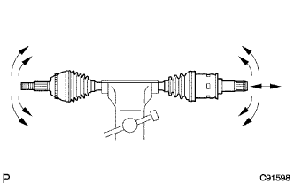
Check that there is no excessive play in the radial direction of the outboard joint.
-
Check that the inboard joint slides smoothly in the thrust direction.
-
Check that there is no excessive play in the radial direction of the inboard joint.
-
Check the boots for damage.
-
Text in Illustration *A LH Side *B RH Side Check whether the drive shaft dimensions (A) are within the following specifications.
Note
Keep the drive shaft assembly level during inspection.
Dimension (A) for TMC Made except TMC Made LH Side 585.2 mm (1.92 ft.) 587.4 mm (1.93 ft.) RH Side 910.0 mm (2.99 ft.) 906.6 mm (2.97 ft.)
-