FRONT DRIVE SHAFT ASSEMBLY (for 2AR-FE) DISASSEMBLY

-
REMOVE FRONT NO. 2 AXLE INBOARD JOINT BOOT CLAMP (for TMC Made)
-
for One Touch Type:
-
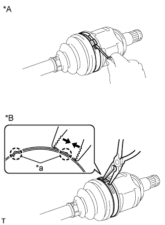
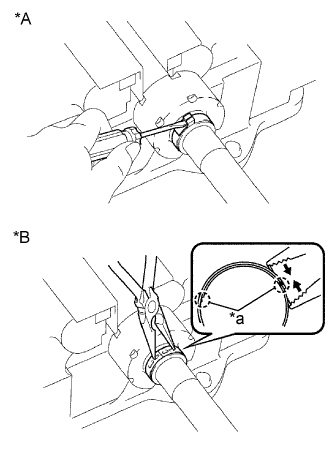
Text in Illustration *A for One Touch Type *B for Claw Engagement Type Using a screwdriver, remove the front No. 2 axle inboard joint boot clamp.
-
-
for Claw Engagement Type:
-
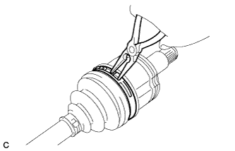
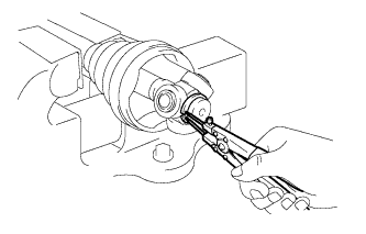
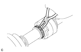
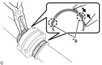
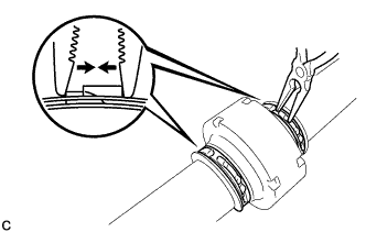
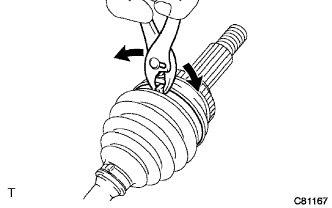
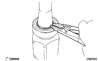
Using needle-nose pliers, remove the front No. 2 axle inboard joint boot clamp.
Text in Illustration *a claws
-
-
-
REMOVE FRONT NO. 2 AXLE INBOARD JOINT BOOT CLAMP (except TMC Made)
-
Using needle-nose pliers, remove the front No. 2 axle inboard joint boot clamp.
-
-
REMOVE FRONT AXLE INBOARD JOINT BOOT CLAMP (for TMC Made)
Tech Tips
Perform the same procedure as for the front No. 2 axle inboard joint boot clamp.
-
REMOVE FRONT AXLE INBOARD JOINT BOOT CLAMP (except TMC Made)
Tech Tips
Perform the same procedure as for the front No. 2 axle inboard joint boot clamp.
-
SEPARATE FRONT AXLE INBOARD JOINT BOOT
-
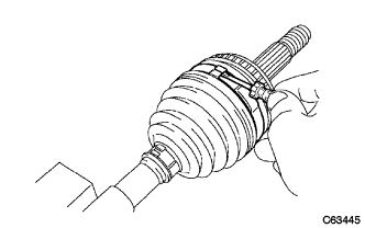
Separate the front axle inboard joint boot from the front drive inboard joint assembly.
-
-
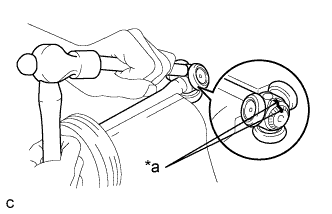
REMOVE FRONT DRIVE INBOARD JOINT ASSEMBLY (for TMC Made)
-
Remove the old grease from the front drive inboard joint assembly.
-
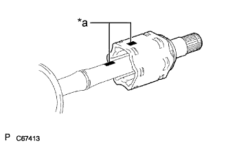
Text in Illustration *a Matchmark Put matchmarks on the front drive inboard joint assembly and front drive outboard joint shaft assembly.
Note
Do not use a punch for the marks.
-
Remove the front drive inboard joint assembly from the front drive outboard joint shaft assembly.
-
Hold the drive shaft in a vise between aluminum plates.
Note
Do not overtighten the vise.
-
Using a snap ring expander, remove the shaft snap ring from the front drive outboard joint shaft assembly.
-
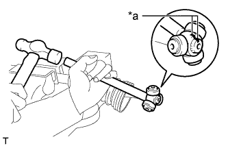
Text in Illustration *a Matchmark Put matchmarks on the front drive outboard joint shaft assembly and tripod joint.
Note
Do not use a punch for the marks.
-
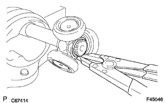
Using a brass bar and a hammer, tap out the tripod joint from the front drive outboard joint shaft assembly.
Note
-
Do not tap the rollers.
-
Do not drop the tripod joint.
-
-
-
REMOVE FRONT DRIVE INBOARD JOINT ASSEMBLY (except TMC Made)
-
Remove the old grease from the front drive inboard joint assembly.
-
Text in Illustration *a Matchmark Put matchmarks on the front drive inboard joint assembly and front drive outboard joint shaft assembly.
Note
Do not use a punch for the marks.
-
Remove the front drive inboard joint assembly from the front drive outboard joint shaft assembly.
-
Hold the drive shaft in a vise between aluminum plates.
Note
Do not overtighten the vise.
-
Using a snap ring expander, remove the shaft snap ring from the front drive outboard joint shaft assembly.
-
Text in Illustration *a Matchmark Put matchmarks on the front drive outboard joint shaft assembly and tripod joint.
Note
Do not use a punch for the marks.
-
Using a brass bar and a hammer, tap out the tripod joint from the front drive outboard joint shaft assembly.
Note
-
Do not tap the rollers.
-
Do not drop the tripod joint.
-
-
-
REMOVE FRONT AXLE INBOARD JOINT BOOT
-
Remove the front No. 2 axle inboard joint boot clamp, front axle inboard joint boot and front axle inboard joint boot clamp.
-
-
REMOVE FRONT DRIVE SHAFT DAMPER (w/ 1 Clamp)
-
for TMC Made One Touch Type:
-
Text in Illustration *A for One Touch Type *B for Claw Engagement Type Using a screwdriver, remove the front drive shaft damper clamp.
-
-
for TMC Made Claw Engagement Type:
-
Using needle-nose pliers, remove the front drive shaft damper clamp.
-
-
except TMC Made:
-
Text in Illustration *a claws Using needle-nose pliers, remove the front drive shaft damper clamp.
-
-
Remove the front drive shaft damper.
-
-
REMOVE FRONT DRIVE SHAFT DAMPER (w/ 2 Clamps)
-
for TMC Made:
-
Text in Illustration *a claws Using needle-nose pliers, remove the 2 front drive shaft damper clamps.
-
-
except TMC Made:
-
Using needle-nose pliers, remove the 2 front drive shaft damper clamps.
-
-
Remove the front drive shaft damper.
-
-
REMOVE FRONT NO. 2 AXLE OUTBOARD JOINT BOOT CLAMP (for TMC Made)
-
Using a screwdriver, remove the front No. 2 axle outboard joint boot clamp.
-
-
REMOVE FRONT NO. 2 AXLE OUTBOARD JOINT BOOT CLAMP (except TMC Made)
-
Using pliers, remove the front No. 2 axle outboard joint boot clamp.
-
-
REMOVE FRONT AXLE OUTBOARD JOINT BOOT CLAMP (for TMC Made)
Tech Tips
Perform the same procedure as for the front No. 2 axle outboard joint boot clamp.
-
REMOVE FRONT AXLE OUTBOARD JOINT BOOT CLAMP (except TMC Made)
Tech Tips
Perform the same procedure as for the front No. 2 axle outboard joint boot clamp.
-
REMOVE FRONT AXLE OUTBOARD JOINT BOOT
-
Remove the front axle outboard joint boot clamp, front axle outboard joint boot and front No. 2 axle outboard joint boot clamp from the front drive outboard joint shaft assembly.
-
Remove the grease from the outboard joint.
-
-
REMOVE FRONT DRIVE SHAFT DUST COVER LH
-
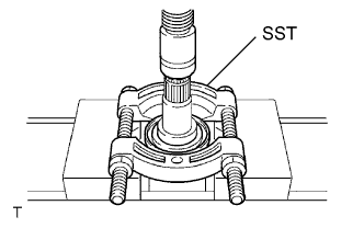
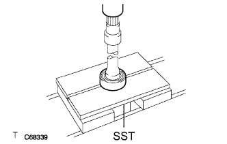
Using SST and a press, remove the front drive shaft dust cover LH.
- SST
- 09950-00020
Note
-
Be careful not to drop the front drive inboard joint assembly.
-
Do not overtighten SST.
-
-
REMOVE FRONT DRIVE SHAFT DUST COVER RH
-
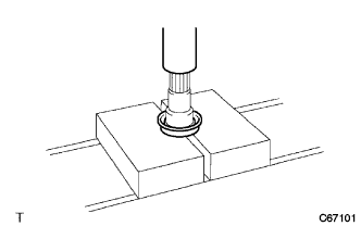
Using a press, remove the front drive shaft dust cover RH.
Note
Be careful not to drop the front drive inboard joint assembly.
-
-
REMOVE FRONT DRIVE SHAFT DUST COVER (for RH Side)
-
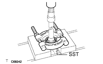
Using SST and a press, remove the front drive shaft dust cover.
- SST
- 09950-00020
Note
-
Be careful not to drop the front drive inboard joint assembly.
-
Do not overtighten SST.
-
-
REMOVE FRONT DRIVE SHAFT BEARING (for RH Side)
-
Using a snap ring expander, remove the drive shaft hole snap ring.
-
Using SST and a press, remove the front drive shaft bearing.
- SST
- 09527-10011
Note
Be careful not to drop the front drive inboard joint assembly.
-