FRONT DRIVE SHAFT ASSEMBLY (for 1AZ-FE) INSTALLATION

-
INSTALL FRONT DRIVE SHAFT ASSEMBLY LH
-
Coat the spline of the front drive inboard joint assembly with ATF.
-
Coat the lip of the differential side bearing retainer oil seal with MP grease.
-
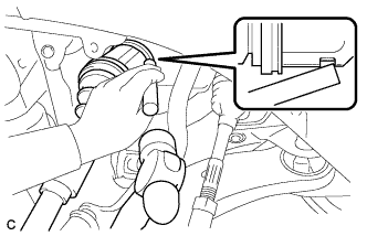
Align the inboard joint splines, and using a brass bar and a hammer, install the front drive shaft assembly LH.
Note
-
Face the end gap of the front drive shaft hole snap ring LH downward.
-
Do not damage the differential side bearing retainer oil seal.
-
Do not damage the front axle inboard joint boot.
-
Make sure to center the front drive shaft assembly LH during installation to prevent damage to the front drive shaft hole snap ring LH.
Tech Tips
Confirm whether the drive shaft is securely driven in by checking the reaction force and sound.
-
-
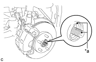
Text in Illustration *a Matchmark Align the matchmarks and install the front drive shaft assembly LH to the front axle hub sub-assembly.
Note
Be careful not to damage the front axle outboard joint boot or speed sensor rotor.
-
-
INSTALL FRONT DRIVE SHAFT ASSEMBLY RH
-
Coat the spline of the front drive inboard joint assembly with ATF.
-
Coat the lip of the transaxle housing oil seal with MP grease.
-
Install a new bearing bracket hole snap ring to the front drive shaft assembly RH.
-
Install the front drive shaft assembly RH.
Note
-
Do not damage the transaxle housing oil seal.
-
When inserting the front drive shaft assembly RH, keep it level.
-
-
Install the bearing bracket hole snap ring and a new bolt.
- Torque:
- 32 N*m { 330 kgf*cm, 24 ft.*lbf }
-
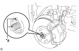
Text in Illustration *a Matchmark Align the matchmarks and install the front drive shaft assembly RH to the front axle hub sub-assembly.
Note
Be careful not to damage the front axle outboard joint boot or speed sensor rotor.
-
-
CONNECT FRONT LOWER NO. 1 SUSPENSION ARM SUB-ASSEMBLY
-
Connect the front lower No. 1 suspension arm sub-assembly to the front lower ball joint assembly with the bolt and 2 nuts.
- Torque:
- 75 N*m { 765 kgf*cm, 55 ft.*lbf }
-
-
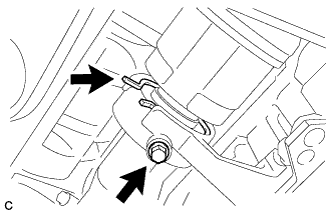
CONNECT TIE ROD ASSEMBLY
-
Connect the tie rod assembly LH to the steering knuckle with the nut.
- Torque:
- 49 N*m { 500 kgf*cm, 36 ft.*lbf }
-
Install a new cotter pin.
Note
Further tighten the nut up to 60° if the holes for the cotter pin are not aligned.
-
-
INSTALL FRONT SPEED SENSOR
-
Install the front speed sensor and front flexible hose to the front shock absorber assembly with the bolt and clamp.
- Torque:
- 19 N*m { 192 kgf*cm, 14 ft.*lbf }
Note
Do not twist the front speed sensor when installing it.
Tech Tips
Install the speed sensor harness bracket first and then the front flexible hose.
-
Install the front speed sensor to the steering knuckle with the bolt.
- Torque:
- 8.5 N*m { 87 kgf*cm, 75 in.*lbf }
Note
Do not twist the front speed sensor when installing it.
-
-
INSTALL FRONT STABILIZER LINK ASSEMBLY
-
for Steel Type:
-
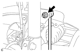
Install the front stabilizer link assembly to the front shock absorber assembly with the nut.
- Torque:
- 74 N*m { 755 kgf*cm, 55 ft.*lbf }
If the ball joint turns together with the nut, use a hexagon wrench to hold the stud bolt.
-
-
for Aluminum Type:
-
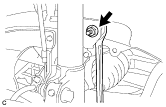
Install the front stabilizer link assembly to the front shock absorber assembly with the nut.
- Torque:
- 74 N*m { 755 kgf*cm, 55 ft.*lbf }
If the ball joint turns together with the nut, use a wrench to hold the stud bolt.
-
-
-
INSTALL FRONT AXLE SHAFT NUT
-
Clean the threaded parts on the front drive shaft assembly and a new axle shaft nut using a non-residue solvent.
Note
-
Be sure to perform this work even when using a new drive shaft.
-
Keep the threaded parts free of oil and foreign matter.
-
-
Using a socket wrench (30 mm), install the front axle shaft nut.
- Torque:
- 294 N*m { 2998 kgf*cm, 217 ft.*lbf }
-
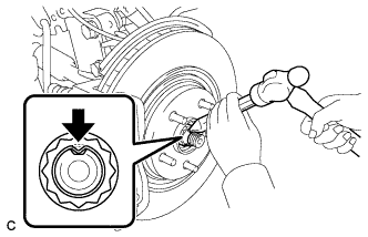
Using a chisel and hammer, stake the front axle shaft nut.
-
-
INSTALL FRONT WHEELS
- Torque:
- 103 N*m { 1049 kgf*cm, 76 ft.*lbf }
-
ADD AUTOMATIC TRANSAXLE FLUID
-
INSPECT TRANSAXLE FLUID LEVEL
Tech Tips
Drive the vehicle so that the engine and transaxle are at normal operating temperature.
Fluid temperature 70 to 80°C (158 to 176°F)
-
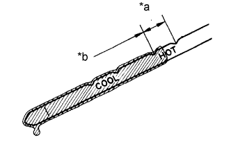
Text in Illustration *a OK if hot *b Add if hot Park the vehicle on a level surface and apply the parking brake.
-
With the engine idling and the brake pedal depressed, move the shift lever to all positions from P to L. Then return it to P.
-
Pull out the dipstick and wipe it clean.
-
Push the dipstick back fully into the pipe.
-
Pull the dipstick out again and check that the fluid level is within the HOT range. If the fluid level is below the HOT range, add new fluid and recheck the fluid level. If the fluid level exceeds the HOT range, drain the fluid once, add a proper amount of new fluid and recheck the fluid level.
Note
Use Toyota Genuine ATF WS.
-
-
INSPECT FOR TRANSAXLE FLUID LEAK
-
INSTALL FRONT FENDER APRON SEAL LH
-
INSTALL FRONT FENDER APRON SEAL RH
-
INSTALL ENGINE UNDER COVER LH
-
INSTALL FRONT WHEEL OPENING EXTENSION PAD LH
-
INSTALL ENGINE UNDER COVER RH
-
INSTALL FRONT WHEEL OPENING EXTENSION PAD RH
-
ADJUST FRONT WHEEL ALIGNMENT
-
CHECK FOR SPEED SENSOR SIGNAL