SHIFT LEVER REMOVAL

-
REMOVE CONSOLE BOX ASSEMBLY
-
REMOVE FRONT DOOR SCUFF PLATE LH
-
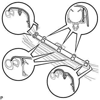
Disengage the 10 claws and remove the front door scuff plate LH.
-
-
REMOVE COWL SIDE TRIM SUB-ASSEMBLY LH
-
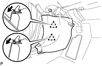
Remove the clip.
-
Disengage the 2 clips and remove the cowl side trim sub-assembly LH.
-
-
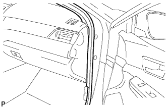
DISCONNECT FRONT DOOR OPENING TRIM WEATHERSTRIP LH
-
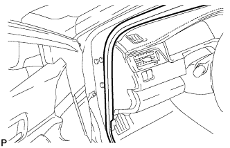
Disconnect the front door opening trim weatherstrip LH.
-
-
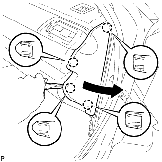
REMOVE INSTRUMENT SIDE PANEL LH
-
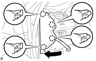
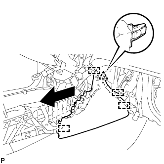
Using a moulding remover, disengage the 4 claws as shown in the illustration.
-
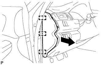
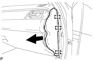
Disengage the 3 guides and remove the instrument side panel LH as shown in the illustration.
-
-
DISCONNECT HOOD LOCK CONTROL LEVER SUB-ASSEMBLY
-
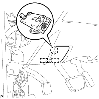
Disengage the claw and 2 guides to disconnect the hood lock control lever sub-assembly.
-
-
REMOVE INSTRUMENT PANEL SUB-ASSEMBLY
-
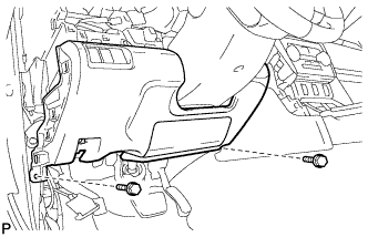
Remove the 2 bolts <B>.
-
w/o Driver Side Knee Airbag:
-
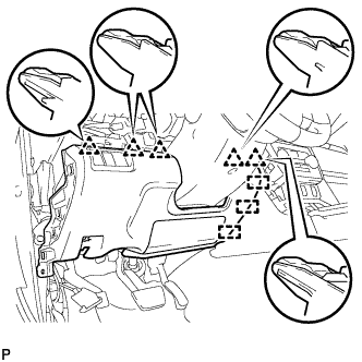
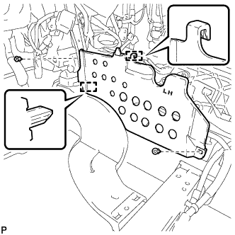
Disengage the 5 clips and 3 guides to remove the instrument panel sub-assembly.
-
-
w/ Driver Side Knee Airbag:
-
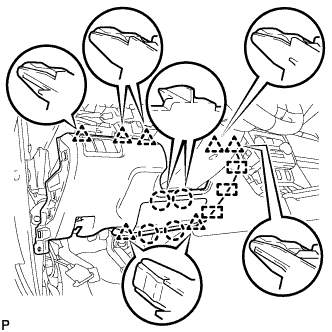
Disengage the 4 claws, 7 clips and 3 guides to remove the instrument panel sub-assembly.
-
-
-
REMOVE FRONT DOOR SCUFF PLATE RH
Tech Tips
Use the same procedure as for the LH side.
-
REMOVE COWL SIDE TRIM SUB-ASSEMBLY RH
Tech Tips
Use the same procedure as for the LH side.
-
DISCONNECT FRONT DOOR OPENING TRIM WEATHERSTRIP RH
-
Disconnect the front door opening trim weatherstrip RH.
-
-
REMOVE INSTRUMENT SIDE PANEL RH
-
Using a moulding remover, disengage the 4 claws as shown in the illustration.
-
Disengage the 3 guides to remove the instrument side panel RH as shown in the illustration.
-
-
REMOVE NO. 2 INSTRUMENT PANEL UNDER COVER SUB-ASSEMBLY
-
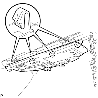
Disengage the 4 claws.
-
Disengage the 2 guides.
-
Disconnect the connector to remove the No. 2 instrument panel under cover sub-assembly.
-
-
REMOVE LOWER INSTRUMENT PANEL SUB-ASSEMBLY
-
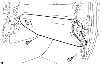
Remove the bolt <B> and screw <C>.
-
Open the lower instrument panel door.
-
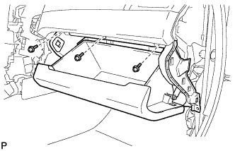
Remove the 3 screws <C>.
-
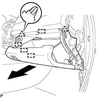
Disengage the 2 clips, 4 guides and remove the lower instrument panel sub-assembly as shown in the illustration.
-
-
REMOVE FRONT CONSOLE UPPER PANEL GARNISH
-
for Blank Type:
-
Disengage the 2 claws and remove the front console upper panel garnish as shown in the illustration.
-
-
for 3 Switch Hole Type:
-
Disengage the 2 claws as shown in the illustration.
-
Disconnect the each connector to remove the front console upper panel garnish.
-
-
-
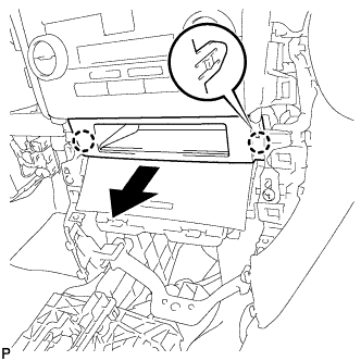
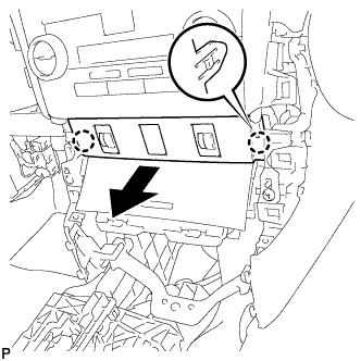
REMOVE FRONT ASH RECEPTACLE ASSEMBLY
-
Remove the 2 screws <C>.
-
Disengage the 2 clips as shown in the illustration.
-
Disconnect each connector to remove the front ash receptacle assembly.
-
-
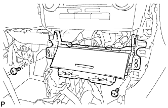
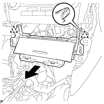
REMOVE FRONT NO. 2 CONSOLE BOX INSERT
-
for LHD:
-
Disengage the 2 claws to disconnect the room temperature sensor from the front No. 2 console box insert.
-
-
Remove the 2 screws <C>.
-
Disengage the clip and 4 guides to remove the front No. 2 console box insert as shown in the illustration.
-
-
REMOVE CONSOLE BOX INSERT
-
for RHD:
-

Disengage the 2 claws to disconnect the room temperature sensor from the console box insert.
-
-
Remove the 2 screws <C>.
-
Disengage the clip and 4 guides to remove the console box insert as shown in the illustration.
-
-
REMOVE FLOOR CARPET BRACKET LH
-
Remove the 2 clips.
-
Disengage the 2 guides to remove the floor carpet bracket LH.
-
-
REMOVE NO. 1 CONSOLE BOX MOUNTING BRACKET
-
Remove the screw and No. 1 console box mounting bracket from the lower shift lever assembly.
-
-
REMOVE NO. 1 CONSOLE BOX DUCT
-
Remove the clip and No. 1 console box duct.
-
-
REMOVE LOWER SHIFT LEVER ASSEMBLY
-
Move the shift lever to N.
-
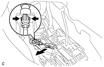
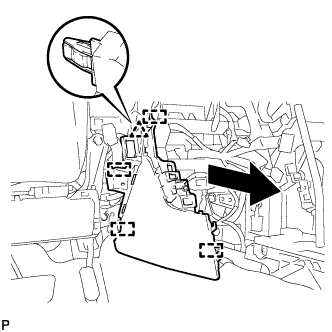
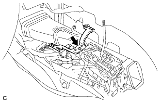
Disconnect the end of transmission control cable assembly from the lower shift lever assembly.
-
Disengage the 2 claws and disconnect the transmission control cable assembly from the lower shift lever assembly.
-
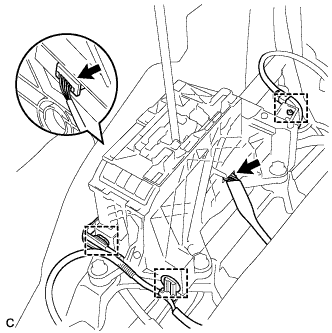
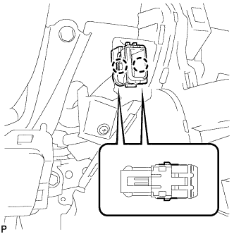
Disconnect the 3 clamps and 2 connectors.
-
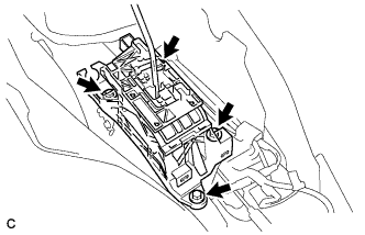
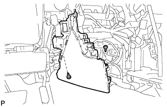
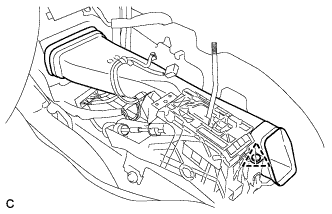
Remove the 4 bolts and lower shift lever assembly.
-
-
REMOVE SHIFT LEVER SUPPORT
-
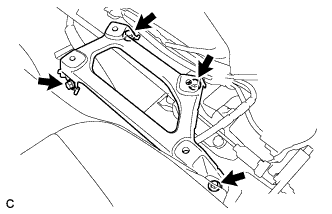
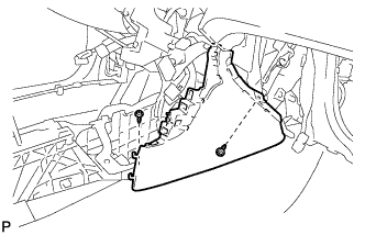
Remove the 4 bolts and shift lever support.
-