AUTOMATIC TRANSAXLE UNIT INSPECTION

-
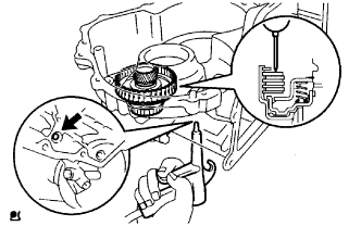
INSPECT AUTOMATIC TRANSAXLE OIL PAN SUB-ASSEMBLY
-
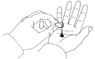
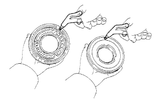
Remove the magnets and use them to collect any steel chips. Examine the chips and particles in the pan and on the magnets to determine what type of wear has occurred in the transaxle.
Steel (magnetic): bearing, gear and plate wear
Brass (non-magnetic): bush wear
-
-
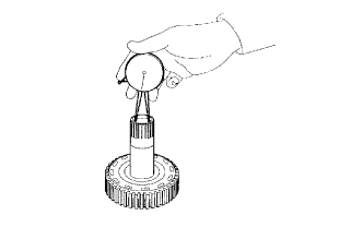
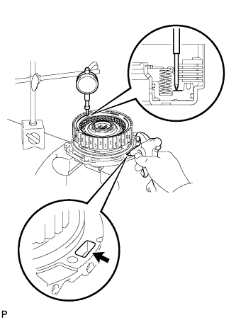
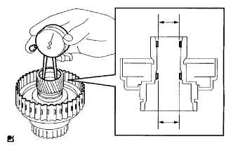
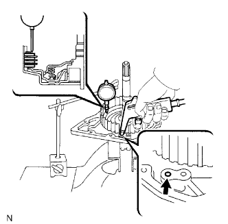
INSPECT INPUT SHAFT END PLAY
-
Secure the transaxle case with the oil pump side facing up.
-
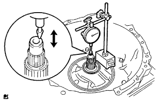
Using a dial indicator, measure the input shaft end play.
Standard end play 0.262 to 1.25 mm (0.0103 to 0.0492 in.) If the end play is not as specified, replace the stator shaft thrust needle roller bearing and the forward clutch hub thrust needle roller bearing.
-
-
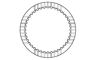
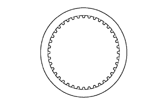
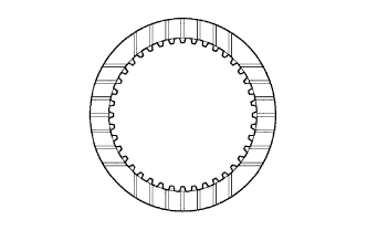
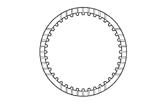
INSPECT NO. 2 UNDERDRIVE CLUTCH DISC
-
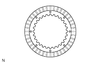
Check if the sliding surface of the No. 2 underdrive clutch disc, plate and flange are worn or burnt.
If necessary, replace them.
Note
-
If the lining of the No. 2 underdrive clutch disc is peeling off or discolored, or even if a part of the groove is defaced, replace all No. 2 underdrive clutch discs.
-
Before assembling new No. 2 underdrive clutch discs, soak them in ATF for at least 15 minutes.
-
-
-
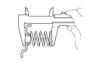
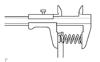
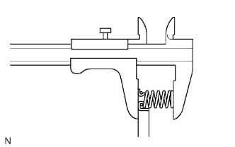
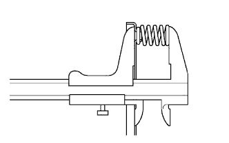
INSPECT UNDERDRIVE BRAKE RETURN SPRING SUB-ASSEMBLY
-
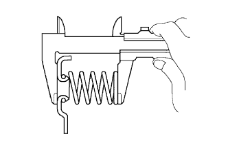
Using a vernier caliper, measure the free length of the underdrive brake return spring sub-assembly together with the spring seat.
Standard free length 14.04 mm (0.553 in.) If the free length is shorter than the standard free length, replace the underdrive brake return spring sub-assembly.
-
-
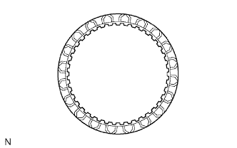
INSPECT 2ND BRAKE CLUTCH DISC
-
Check if the sliding surface of the 2nd brake clutch disc, plate and flange are worn or burnt.
If necessary, replace them.
Note
-
If the lining of the 2nd brake clutch disc is peeling off or discolored, or even if a part of the printed number is defaced, replace all 2nd brake clutch discs.
-
Before assembling new 2nd brake clutch discs, soak them in ATF for at least 15 minutes.
-
-
-
INSPECT 1ST AND REVERSE BRAKE CLUTCH DISC
-
Check if the sliding surface of the 1st and reverse brake clutch disc, plate and flange are worn or burnt.
If necessary, replace them.
Note
-
If the lining of the 1st and reverse brake clutch disc is peeling off or discolored, or even if a part of the groove is defaced, replace all 1st and reverse brake clutch discs.
-
Before assembling new 1st and reverse brake clutch discs, soak them in ATF for at least 15 minutes.
-
-
-
INSPECT 1ST AND REVERSE BRAKE RETURN SPRING SUB-ASSEMBLY
-
Using a vernier caliper, measure the free length of the 1st and reverse brake return spring sub-assembly together with the spring seat.
Standard free length 15.53 mm (0.611 in.) If the free length is shorter than the standard free length, replace the 1st and reverse brake return spring sub-assembly.
-
-
INSPECT MULTIPLE DISC CLUTCH HUB
-
Using a caliper gauge, measure the inside diameter of the multiple disc clutch hub.
Standard inside diameter 23.025 to 23.046 mm (0.9065 to 0.9073 in.) Maximum inside diameter 23.09 mm (0.9091 in.) Note
Check the contact surface of the bush in the direct clutch shaft. If any scratch or discolor is identified, replace the direct clutch sub-assembly with a new one.
If the inside diameter is greater than the maximum, replace the multiple disc clutch hub.
-
-
INSPECT PACK CLEARANCE OF FORWARD CLUTCH
-
Install the forward clutch on the oil pump.
Note
Be careful not to damage the oil seal ring of the oil pump.
-
Using a dial indicator, measure the forward clutch piston stroke while applying and releasing compressed air (392 kPa, 4.0 kgf/cm2, 57 psi).
Standard piston stroke 1.41 to 1.75 mm (0.0555 to 0.0688 in.) If the piston stroke is less than the minimum, the parts may have been assembled incorrectly. Check and reassemble again.
If the clearance is not as specified, select another flange.
Tech Tips
There are 7 different thicknesses of flanges.
Standard Flange Thickness Mark Thickness Mark Thickness 0 2.85 mm (0.112 in.) 4 3.45 mm (0.1358 in.) 1 3.00 mm (0.1181 in.) 5 3.60 mm (0.1417 in.) 2 3.15 mm (0.1240 in.) 6 3.75 mm (0.147 in.) 3 3.30 mm (0.1299 in.) - -
-
-
INSPECT FORWARD MULTIPLE DISC CLUTCH DISC
-
Check if the sliding surface of the forward multiple disc clutch disc, plate and flange are worn or burnt.
If necessary, replace them.
Note
-
If the lining of the forward multiple disc clutch disc is peeling off or discolored, replace all forward multiple disc clutch discs.
-
Before assembling new forward multiple disc clutch discs, soak them in ATF for at least 15 minutes.
-
-
-
INSPECT FORWARD CLUTCH RETURN SPRING SUB-ASSEMBLY
-
Using a vernier caliper, measure the free length of the forward clutch return spring sub-assembly together with the spring seat.
Standard free length 28.23 mm (1.1114 in.) If the result is not as specified, replace the forward clutch return spring sub-assembly.
-
-
INSPECT FORWARD CLUTCH PISTON SUB-ASSEMBLY
-
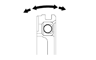
Shake the forward clutch piston sub-assembly to check that the check ball is not stuck.
-
Check that the valve does not leak when applying low pressure compressed air (392 kPa, 4.0 kgf/cm2, 57 psi).
-
-
INSPECT UNDERDRIVE PLANETARY GEAR PRELOAD
-
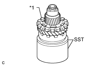
Text in Illustration *1 Underdrive Planetary Gear Using SST, secure the underdrive planetary gear assembly.
- SST
- 09387-00050
- 09495-65040
-
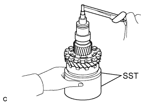
Using SST and a torque wrench, measure the turning torque of the underdrive planetary gear assembly while turning the torque wrench at 60 rpm.
- SST
- 09387-00050
- 09495-65040
Turning torque at 60 rpm 0.28 to 0.89 N*m (2.9 to 9.1 kgf*cm, 2.478 to 7.877 in.*lbf) Tech Tips
Use a torque wrench with a fulcrum length of 160 mm (6.30 in.).
-
-
INSPECT UNDERDRIVE CLUTCH PACK CLEARANCE
-
Install the underdrive clutch to the transaxle case.
Note
Be careful not to damage the oil seal rings.
-
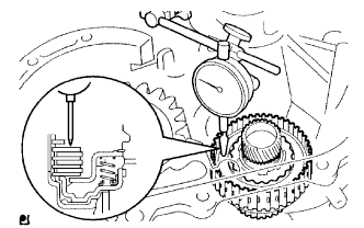
Install a dial indicator as shown in the illustration.
-
Measure the underdrive clutch piston stroke while applying and releasing compressed air (392 kPa, 4.0 kgf/cm2, 57 psi).
Standard pack clearance 1.51 to 1.71 mm (0.0594 to 0.0673 in.) If the pack clearance is not as specified, inspect the discs, plates and flange.
If the pack clearance is less than the minimum, the parts may have been assembled incorrectly, so check and reassemble again.
If the pack clearance is not as specified, select another flange.
Tech Tips
There are 7 flanges in different thickness.
Standard Flange Thickness Mark Thickness Mark Thickness A 3.0 mm (0.118 in.) G 3.1 mm (0.122 in.) B 3.2 mm (0.126 in.) H 3.3 mm (0.130 in.) C 3.4 mm (0.134 in.) J 3.5 mm (0.138 in.) F 2.9 mm (0.114 in.) - -
-
-
INSPECT NO. 1 UNDERDRIVE CLUTCH DISC
-
Check to see if the sliding surface of the No. 1 underdrive clutch disc, plate and flange are worn or burnt. If necessary, replace them.
Note
-
If the lining of the No. 1 underdrive clutch disc is peeling off or discolored, replace all No. 1 underdrive clutch discs.
-
Before assembling new No. 1 underdrive clutch discs, soak them in ATF for at least 15 minutes.
-
-
-
INSPECT UNDERDRIVE CLUTCH RETURN SPRING SUB-ASSEMBLY
-
Using a vernier caliper, measure the free length of the underdrive clutch return spring sub-assembly together with the spring seat.
Standard free length 17.14 mm (0.6748 in.) If the result is not as specified, replace the underdrive clutch return spring sub-assembly.
-
-
INSPECT UNDERDRIVE CLUTCH DRUM SUB-ASSEMBLY
-
Using a caliper gauge, measure the inside diameter of the underdrive clutch drum bush.
Standard drum bushing 32.56 to 32.58 mm (1.2818 to 1.2826 in.) Maximum drum bushing 32.63 mm (1.2846 in.) If the inside diameter is greater than the maximum, replace the underdrive clutch drum sub-assembly.
-
-
INSPECT PACK CLEARANCE OF DIRECT CLUTCH
-
Install the direct clutch and needle roller bearing on the transaxle rear cover.
-
Using a dial indicator, measure the direct clutch pack clearance while applying and releasing compressed air (392 kPa, 4.0 kgf/cm2, 57 psi).
Standard pack clearance 0.652 to 0.872 mm (0.0257 to 0.0343 in.) If the pack clearance is not as specified, inspect the discs, plates and flange.
If the pack clearance is less than the minimum, the parts may have been assembled incorrectly. Check and reassemble them again.
If the pack clearance is still not as specified, select another flange.
Tech Tips
There are 8 different thicknesses of flanges.
Standard Flange Thickness Mark Thickness Mark Thickness 0 2.9 mm (0.114 in.) 4 3.3 mm (0.130 in.) 1 3.0 mm (0.118 in.) 5 3.4 mm (0.134 in.) 2 3.1 mm (0.122 in.) 6 3.5 mm (0.138 in.) 3 3.2 mm (0.126 in.) 7 3.6 mm (0.142 in.)
-
-
INSPECT DIRECT MULTIPLE DISC CLUTCH DISC
-
Check if the sliding surface of the direct multiple disc clutch disc, plate and flange are worn or burnt.
If necessary, replace them.
Note
-
If the lining of the direct multiple disc clutch disc is peeling off or discolored, replace all direct multiple disc clutch discs.
-
Before assembling new direct multiple disc clutch discs, soak them in ATF for at least 15 minutes.
-
-
-
INSPECT DIRECT CLUTCH RETURN SPRING SUB-ASSEMBLY
-

Using a vernier caliper, measure the free length of the direct clutch return spring sub-assembly together with the spring seat.
Standard free length 22.58 mm (0.8890 in.) If the result is not as specified, replace the direct clutch return spring sub-assembly.
-
-
INSPECT 2ND BRAKE PISTON RETURN SPRING SUB-ASSEMBLY
-
Using a vernier caliper, measure the free length of the 2nd brake piston return spring sub-assembly together with the spring seat.
Standard free length 16.61 mm (0.6539 in.) If the result is not as specified, replace the 2nd brake piston return spring sub-assembly.
-