PARK / NEUTRAL POSITION SWITCH INSTALLATION

-
INSTALL PARK/NEUTRAL POSITION SWITCH ASSEMBLY
-
Install the park/neutral position switch assembly to the automatic transaxle.
-
Temporarily install the 2 bolts.
-
Replace the lock plate with a new one and tighten the nut.
- Torque:
- 6.9 N*m { 70 kgf*cm, 61 in.*lbf }
-
Temporarily install the control shaft lever.
-
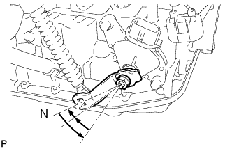
Turn the lever counterclockwise until it stops, then turn it clockwise 2 notches.
-
Remove the control shaft lever.
-
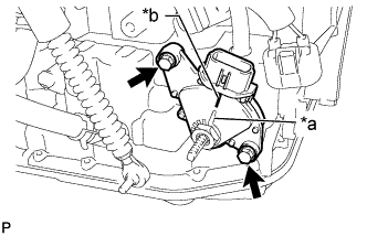
Text in Illustration *a Nut Stopper Protrusion *b Neutral Basic Line Align the nut stopper protrusion with the neutral basic line.
-
Hold the switch in that position and tighten the 2 bolts.
- Torque:
- 5.4 N*m { 55 kgf*cm, 48 in.*lbf }
Note
After installing the park/neutral position switch assembly, confirm that the nut stopper protrusion and neutral basic line on the switch are aligned.
-
Using a screwdriver, stake the nut with the lock plate.
-
Install the control shaft lever with the nut and washer.
- Torque:
- 13 N*m { 130 kgf*cm, 9 ft.*lbf }
-
Connect the transmission control cable to the No. 1 transmission control cable bracket with a new clip.
-
Connect the transmission control cable assembly to the control shaft lever with the nut.
- Torque:
- 15 N*m { 153 kgf*cm, 11 ft.*lbf }
-
Connect the connector to the park/neutral position switch assembly.
-
-
INSTALL BATTERY TRAY
-
Install the battery tray to the body.
-
-
INSTALL BATTERY
-
Install the battery to the battery tray.
-
Install the battery clamp with the bolt and nut.
- Torque:
- Bolt
- 9.0 N*m { 92 kgf*cm, 80 in.*lbf }
- Nut
- 3.5 N*m { 36 kgf*cm, 31 in.*lbf }
-
Connect the cable to the positive (+) battery terminal.
- Torque:
- 6.0 N*m { 61 kgf*cm, 53 in.*lbf }
-
-
INSTALL AIR CLEANER CASE SUB-ASSEMBLY
-
Install the air cleaner case sub-assembly with the 3 bolts.
- Torque:
- 5.0 N*m { 51 kgf*cm, 44 in.*lbf }
-
Connect the wire harness clamp.
-
-
INSTALL AIR CLEANER CAP SUB-ASSEMBLY
-
Install the air cleaner filter element to the air cleaner case sub-assembly.
-
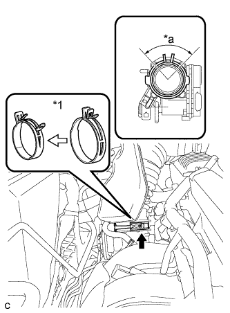
Text in Illustration *1 Air Cleaner Hose Clamp Connect the air cleaner cap sub-assembly to the throttle with motor body assembly and release the lock of the air cleaner hose clamp.
Note
-
Align the groove of the air cleaner cap sub-assembly with the tab of the throttle with motor body assembly and install the hose.
-
Make sure that the tab of the air cleaner hose clamp stays within the range shown by *a.
-
-
Connect the ventilation hose to the cylinder head cover.
-
Install the air cleaner cap sub-assembly and tighten the 2 bolts.
- Torque:
- 5.0 N*m { 51 kgf*cm, 44 in.*lbf }
-
Connect the wire harness clamp.
-
Connect the mass air flow meter connector.
-
Connect the purge line hose to the 2 clamps.
-
Connect the 2 vacuum switching valve vacuum hoses.
-
Connect the vacuum switching valve connector.
-
-
INSTALL INLET AIR CLEANER ASSEMBLY
-
Install the inlet air cleaner assembly with the 2 bolts.
- Torque:
- 8.0 N*m { 82 kgf*cm, 71 in.*lbf }
-
-
INSTALL COOL AIR INTAKE DUCT SEAL
-
Install the cool air intake duct seal with the 9 clips.
-
-
CONNECT CABLE TO NEGATIVE BATTERY TERMINAL
Note
When disconnecting the cable, some systems need to be initialized after the cable is reconnected Click here.
-
INSTALL NO. 1 ENGINE COVER SUB-ASSEMBLY
-
Install the No. 1 engine cover sub-assembly with the 2 nuts.
- Torque:
- 9.0 N*m { 92 kgf*cm, 80 in.*lbf }
-
-
INSPECT SHIFT LEVER POSITION
-
When shifting from P to R with the ignition switch ON and the brake pedal depressed, make sure that the shift lever moves smoothly and correctly into P.
-
Start the engine and make sure that the vehicle moves forward when the shift lever is moved from N to D and moves rearward when the shift lever is moved to R.
If the operation cannot be done as specified, inspect the park/neutral position switch assembly and inspect the shift lock control unit.
-
-
ADJUST SHIFT LEVER POSITION
-
Move the shift lever to N.
-
Remove the console box assembly Click here.
-
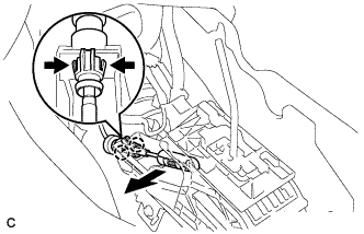
Disconnect the end of transmission control cable assembly from the lower shift lever assembly
-
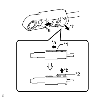
Text in Illustration *1 Slider *2 Lock Piece *a Slide *b Pull Slide the slider of the transmission control cable in the direction indicated by the arrow and pull the lock piece outward.
-
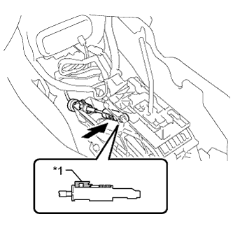
Text in Illustration *1 Lock Piece Install the transmission control cable end to the shift lever assembly.
Note
-
Check that the lock piece is pulled up.
-
Install the cable end all the way to the base of the pin.
-
-
Push the lock piece into the adjuster case.
Note
-
Check that the park/neutral position switch and the shift lever are in neutral.
-
Securely push in the lock piece until the slider lock is engaged.
-
-
After adjusting the shift lever position, check the operation and function of the shift lever. If there is a problem, adjust the position again.
-
Install the console box assembly Click here.
-
-
INSPECT PARK/NEUTRAL POSITION SWITCH ASSEMBLY
-
Apply the parking brake.
-
Turn the ignition switch to ON.
-
Depress the brake pedal and check that the engine starts when the shift lever is in N or P, but does not start in any other position.
-
Check that the back-up light comes on when the shift lever is moved to R, but the light does not operate in any other position. If the operation cannot be done as specified, check the park/neutral position switch assembly for continuity.
-