ENGINE SWITCH INSTALLATION

-
INSTALL ENGINE SWITCH (for RHD)
-
Engage the 2 claws to install the engine switch.
-
-
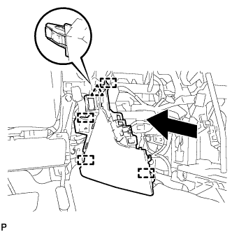
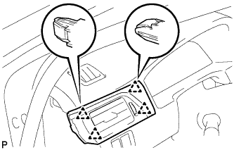
INSTALL UPPER INSTRUMENT PANEL FINISH PANEL (for RHD)
-
w/ Smart Entry and Start System:
-
Connect the connector.
-
-
Engage the 2 claws and 4 clips to install the upper instrument panel finish panel.
-
-
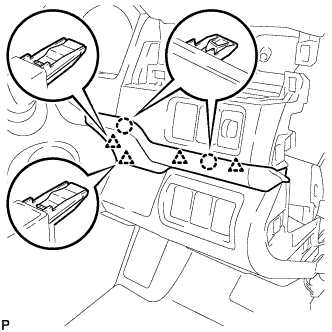
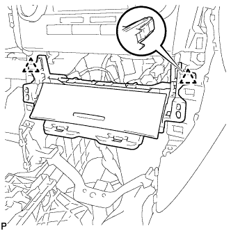
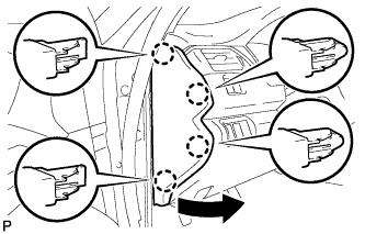
INSTALL INSTRUMENT SIDE PANEL RH (for RHD)
-
Engage the 3 guides as shown in the illustration.
-
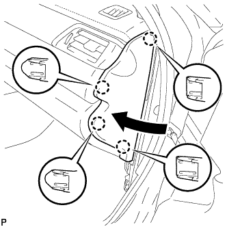
Engage the 4 claws to install the instrument side panel RH as shown in the illustration.
-
-
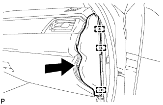
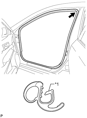
INSTALL FRONT DOOR OPENING TRIM WEATHERSTRIP RH (for RHD)
-
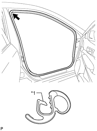
Text in Illustration *1 Alignment Mark (White) Align the alignment mark (White) on the weatherstrip with the protruding portion on the body indicated by the arrow in the illustration, and install the front door opening trim weatherstrip RH.
Note
After installation, check that the corners fit correctly.
-
-
INSTALL COWL SIDE TRIM SUB-ASSEMBLY RH (for RHD)
Tech Tips
Use the same procedure as for the LH side Click here.
-
INSTALL FRONT DOOR SCUFF PLATE RH (for RHD)
Tech Tips
Use the same procedure as for the LH side Click here.
-
INSTALL ENGINE SWITCH (for LHD)
-
Engage the 2 claws to install the engine switch.
-
-
INSTALL LOWER INSTRUMENT PANEL FINISH PANEL ASSEMBLY (for LHD)
-
for LHD with Smart Entry and Start System:
-
Connect the connector.
-
-
Engage the 3 clips and guide to install the lower instrument panel finish panel assembly.
-
-
INSTALL FRONT NO. 2 CONSOLE BOX INSERT (for LHD)
-
Engage the clip and 4 guides as shown in the illustration.
-
Install the front No. 2 console box insert with the 2 screws <C>.
-
for LHD:
-
Engage the 2 claws to connect the room temperature sensor.
-
-
-
INSTALL CONSOLE BOX ASSEMBLY
-
INSTALL FRONT ASH RECEPTACLE ASSEMBLY
-
Connect each connector.
-
Engage the 2 clips.
-
Install the front ash receptacle assembly with the 2 screws <C>.
-
-
INSTALL INSTRUMENT PANEL SUB-ASSEMBLY (for LHD)
-
w/o Driver Side Knee Airbag:
-
Engage the 5 clips and 3 guides.
-
-
w/ Driver Side Knee Airbag:
-
Engage the 4 claws, 7 clips and 3 guides.
-
-
Install the instrument panel sub-assembly with the 2 bolts <B>.
-
-
CONNECT HOOD LOCK CONTROL LEVER SUB-ASSEMBLY (for LHD)
-
Engage the claw and 2 guides to connect the hood lock control lever sub-assembly.
-
-
INSTALL INSTRUMENT CLUSTER FINISH PANEL ASSEMBLY (for LHD)
-
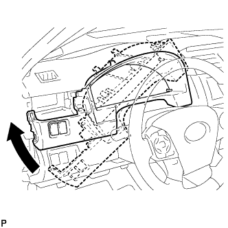
Temporarily install the instrument cluster finish panel assembly as shown in the illustration.
-
Connect each connector.
-
for LHD:
-
Engage the 3 claws, 7 clips and 4 guides.
-
-
for RHD:
-
Engage the 4 claws, 5 clips and 4 guides.
-
-
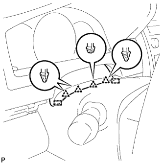
Engage the 4 clips and 2 guides to install the instrument cluster finish panel assembly.
-
-
INSTALL NO. 1 INSTRUMENT PANEL REGISTER ASSEMBLY (for LHD)
-
Engage the 4 clips to install the No. 1 instrument panel register assembly.
-
-
INSTALL INSTRUMENT SIDE PANEL LH (for LHD)
-
Engage the 3 guides.
-
Engage the 4 claws to install the instrument side panel LH as shown in the illustration.
-
-
INSTALL FRONT DOOR OPENING TRIM WEATHERSTRIP LH (for LHD)
-
Text in Illustration *1 Alignment Mark (Yellow) Align the alignment mark (Yellow) on the weatherstrip with the protruding portion on the body indicated by the arrow in the illustration, and install the front door opening trim weatherstrip LH.
Note
After installation, check that the corners fit correctly.
-
-
INSTALL COWL SIDE TRIM SUB-ASSEMBLY LH (for LHD)
-
Engage the 2 clips.
-
Install the cowl side trim sub-assembly LH with the clip.
-
-
INSTALL FRONT DOOR SCUFF PLATE LH (for LHD)
-
Engage the 10 claws to install the front door scuff plate LH.
-
-
INSTALL NAVIGATION RECEIVER ASSEMBLY WITH AIR CONDITIONING CONTROL ASSEMBLY (for LHD)
-
INSTALL RADIO RECEIVER ASSEMBLY WITH AIR CONDITIONING CONTROL ASSEMBLY (for LHD)
-
CONNECT CABLE TO NEGATIVE BATTERY TERMINAL (for Manual Tilt and Manual Telescopic Steering Column)
Note
When disconnecting the cable, some systems need to be initialized after the cable is reconnected Click here.
-
CONNECT CABLE TO NEGATIVE BATTERY TERMINAL (for Power Tilt and Power Telescopic Steering Column)
Note
-
Reset the auto away/return function setting to the previous condition by changing the customize parameter Click here.
-
When disconnecting the cable, some systems need to be initialized after the cable is reconnected Click here.
-