ENGINE SWITCH REMOVAL

-
PRECAUTION
Note
After turning the engine switch off, waiting time may be required before disconnecting the cable from the negative (-) battery terminal. Therefore, make sure to read the disconnecting the cable from the negative (-) battery terminal notices before proceeding with work Click here.
-
DISCONNECT CABLE FROM NEGATIVE BATTERY TERMINAL (for Manual Tilt and Manual Telescopic Steering Column)
Note
When disconnecting the cable, some systems need to be initialized after the cable is reconnected Click here.
-
DISCONNECT CABLE FROM NEGATIVE BATTERY TERMINAL (for Power Tilt and Power Telescopic Steering Column)
-
Disable the auto away/return function by changing the customize parameter Click here.
Note
Record the current customize parameter setting (whether the auto away/return function is enabled or disabled) in order to restore the current setting after finishing this operation.
Tech Tips
Performing the above operation disables the auto away/return function when the engine switch is turned off.
-
Turn the engine switch on (IG). Operate the tilt and telescopic switch to fully extend and lower the steering column assembly.
-
Turn the engine switch off and disconnect the cable from the negative (-) battery terminal.
Note
When disconnecting the cable, some systems need to be initialized after the cable is reconnected Click here.
-
-
REMOVE RADIO RECEIVER ASSEMBLY WITH AIR CONDITIONING CONTROL ASSEMBLY (for LHD)
-
REMOVE NAVIGATION RECEIVER ASSEMBLY WITH AIR CONDITIONING CONTROL ASSEMBLY (for LHD)
-
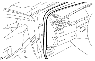
REMOVE FRONT DOOR SCUFF PLATE LH (for LHD)
-
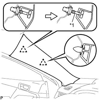
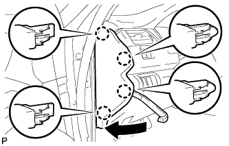
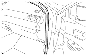
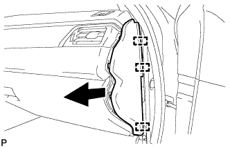
Text in Illustration *1 Front Pillar Garnish Clip Pull the upper part of the garnish toward the inside of the cabin and disengage the garnish from the base of the 2 clips.
Tech Tips
Make the front pillar garnish LH hang down from the front pillar garnish clip.
-
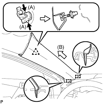
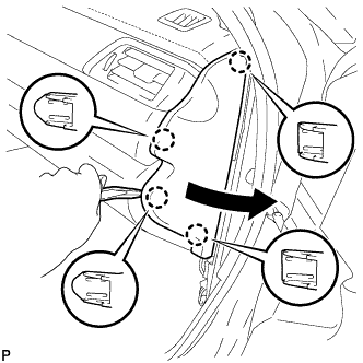
While pushing the tabs on the front pillar garnish clip in the direction indicated by the arrow (A) shown in the illustration, disengage the front pillar garnish clip.
-
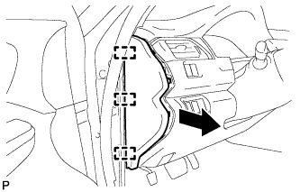
Pull the garnish in the direction indicated by the arrow (B) shown in the illustration to disengage the 2 guides and remove the front pillar garnish LH.
-
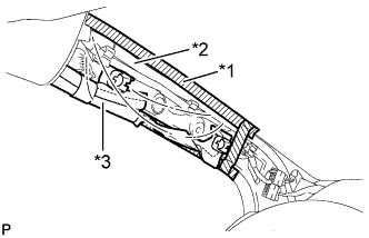
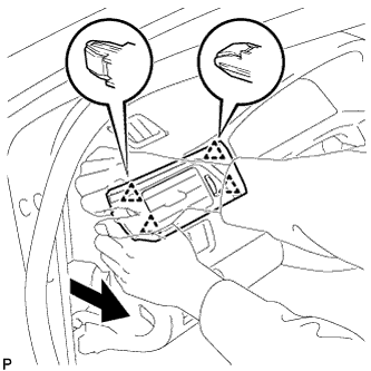
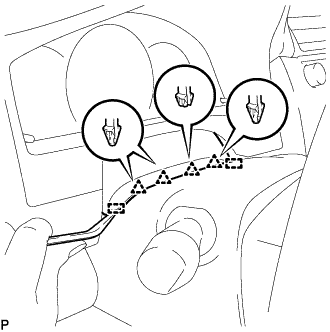
Text in Illustration *1 Adhesive Tape *2 Protective Cover *3 Curtain Shield Airbag Assembly Protect the curtain shield airbag assembly.
-
Cover the airbag with a piece of cloth or nylon and secure the edges of the cover with tape as shown in the illustration.
Note
Cover the curtain shield airbag with a protective cover as soon as the front pillar garnish is removed.
-
-
-
REMOVE COWL SIDE TRIM SUB-ASSEMBLY LH (for LHD)
-
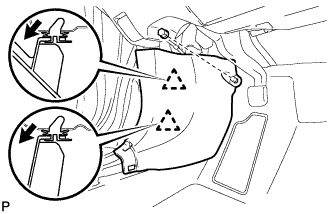
Remove the clip.
-
Disengage the 2 clips and remove the cowl side trim sub-assembly LH.
-
-
DISCONNECT FRONT DOOR OPENING TRIM WEATHERSTRIP LH (for LHD)
-
Disconnect the front door opening trim weatherstrip LH.
-
-
REMOVE INSTRUMENT SIDE PANEL LH (for LHD)
-
Using a moulding remover, disengage the 4 claws as shown in the illustration.
-
Disengage the 3 guides and remove the instrument side panel LH as shown in the illustration.
-
-
REMOVE NO. 1 INSTRUMENT PANEL REGISTER ASSEMBLY (for LHD)
-
Disengage the 4 clips to remove the No. 1 instrument panel register assembly as shown in the illustration.
-
-
REMOVE INSTRUMENT CLUSTER FINISH PANEL ASSEMBLY (for LHD)
-
for Manual Tilt and Manual Telescopic Steering Column:
-
Operate the tilt and telescopic lever to fully extend and lower the steering column assembly.
-
-
Using a moulding remover, disengage the 4 clips and 2 guides.
-
for LHD:
-
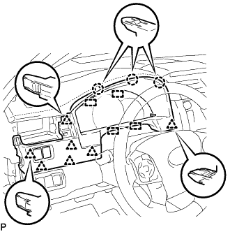
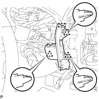
Disengage the 3 claws, 7 clips and 4 guides.
-
-
for RHD:
-
Disengage the 4 claws, 5 clips and 4 guides as shown in the illustration.
-
-
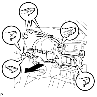
Disconnect each connector.
-
Remove the instrument cluster finish panel assembly as shown in the illustration.
-
-
DISCONNECT HOOD LOCK CONTROL LEVER SUB-ASSEMBLY (for LHD)
-
Disengage the claw and 2 guides to disconnect the hood lock control lever sub-assembly.
-
-
REMOVE INSTRUMENT PANEL SUB-ASSEMBLY (for LHD)
-
Remove the 2 bolts <B>.
-
w/o Driver Side Knee Airbag:
-

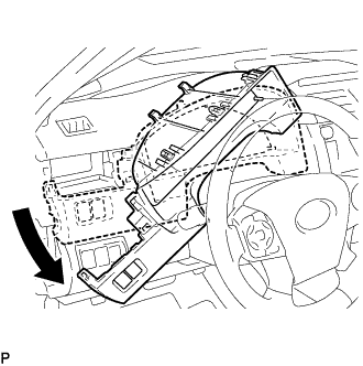
Disengage the 5 clips and 3 guides to remove the instrument panel sub-assembly.
-
-
w/ Driver Side Knee Airbag:
-
Disengage the 4 claws, 7 clips and 3 guides to remove the instrument panel sub-assembly.
-
-
-
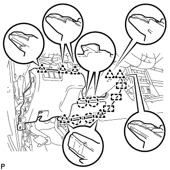
REMOVE FRONT ASH RECEPTACLE ASSEMBLY (for LHD)
-
Remove the 2 screws <C>.
-
Disengage the 2 clips as shown in the illustration.
-
Disconnect each connector to remove the front ash receptacle assembly.
-
-
REMOVE CONSOLE BOX ASSEMBLY (for LHD)
-
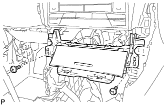
REMOVE FRONT NO. 2 CONSOLE BOX INSERT (for LHD)
-
for LHD:
-
Disengage the 2 claws to disconnect the room temperature sensor from the front No. 2 console box insert.
-
-
Remove the 2 screws <C>.
-
Disengage the clip and 4 guides to remove the front No. 2 console box insert as shown in the illustration.
-
-
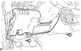
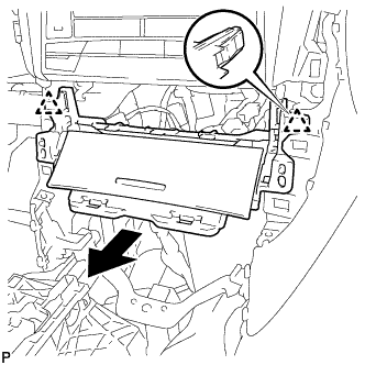
REMOVE LOWER INSTRUMENT PANEL FINISH PANEL ASSEMBLY (for LHD)
-
Disengage the 3 clips and guide to remove the lower instrument panel finish panel assembly.
-
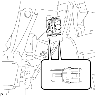
for LHD with Smart Entry and Start System:
-
Disconnect the connector.
-
-
-
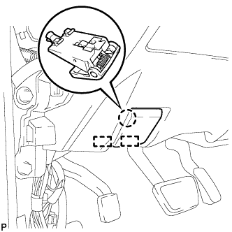
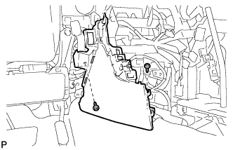
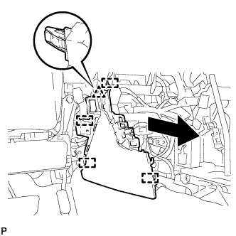
REMOVE ENGINE SWITCH (for LHD)
-
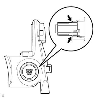
Disengage the 2 claws and remove the engine switch.
-
-
REMOVE FRONT DOOR SCUFF PLATE RH (for RHD)
Tech Tips
Use the same procedure as for the LH side.
-
REMOVE COWL SIDE TRIM SUB-ASSEMBLY RH (for RHD)
Tech Tips
Use the same procedure as for the LH side Click here.
-
DISCONNECT FRONT DOOR OPENING TRIM WEATHERSTRIP RH (for RHD)
-
Disconnect the front door opening trim weatherstrip RH.
-
-
REMOVE INSTRUMENT SIDE PANEL RH (for RHD)
-
Using a moulding remover, disengage the 4 claws as shown in the illustration.
-
Disengage the 3 guides to remove the instrument side panel RH as shown in the illustration.
-
-
REMOVE UPPER INSTRUMENT PANEL FINISH PANEL (for RHD)
-

Disengage the 2 claws and 4 clips to remove the upper instrument panel finish panel as shown in the illustration.
-
w/ Smart Entry and Start System:
-
Disconnect the connector.
-
-
-
REMOVE ENGINE SWITCH (for RHD)
-
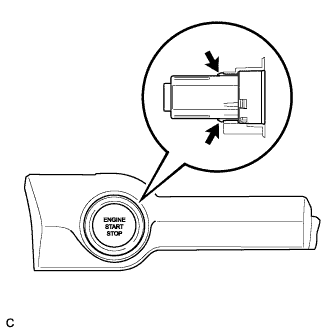
Disengage the 2 claws and remove the engine switch.
-