INTAKE MANIFOLD REMOVAL

-
PRECAUTION
Note
After turning the ignition switch off, waiting time may be required before disconnecting the cable from the negative (-) battery terminal. Therefore, make sure to read the disconnecting the cable from the negative (-) battery terminal notice before proceeding with work Click here.
-
DISCHARGE FUEL SYSTEM PRESSURE
-
DISCONNECT CABLE FROM NEGATIVE BATTERY TERMINAL
Note
When disconnecting the cable, some systems need to be initialized after the cable is reconnected Click here.
-
REMOVE WINDSHIELD WIPER MOTOR AND LINK ASSEMBLY
-
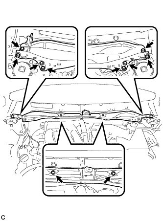
REMOVE FRONT OUTER COWL TOP PANEL SUB-ASSEMBLY (for RHD)
-
Disengage the 2 clamps and separate the wire harness from the front outer cowl top panel sub-assembly.
-
Remove the 10 bolts and front outer cowl top panel sub-assembly.
-
-
REMOVE FRONT OUTER COWL TOP PANEL SUB-ASSEMBLY (for LHD)
-
w/ Windshield Deicer System:
-
Disengage the 2 clamps.
-
Disconnect the connector and separate the wire harness from the front outer cowl top panel sub-assembly.
-
-
w/ Heated Windshield Defroster System:
-
Disengage the 4 clamps.
-
Disconnect the 2 connectors and separate the wire harness from the front outer cowl top panel sub-assembly.
-
-
Disengage the 2 clamps and separate the wire harness from the front outer cowl top panel sub-assembly.
-
Remove the 10 bolts and front outer cowl top panel sub-assembly.
-
-
REMOVE THROTTLE WITH MOTOR BODY ASSEMBLY
-
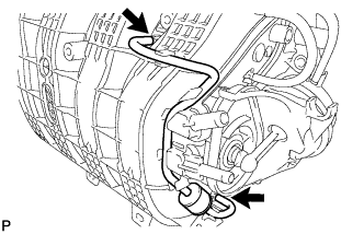
REMOVE VACUUM SWITCHING VALVE ASSEMBLY (for ACIS)
-
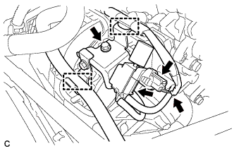
Disconnect the union to connector tube hose and wire harness clamp.
-
Disconnect the 2 vacuum hoses and connector.
-
Remove the bolt and vacuum switching valve assembly.
-
-
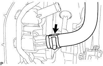
DISCONNECT NO. 2 VENTILATION HOSE
-
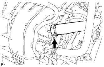
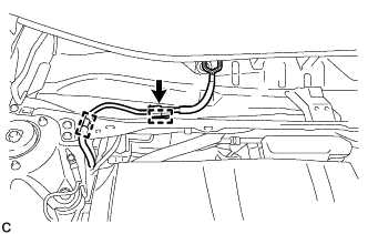
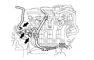
Disconnect the No. 2 ventilation hose from the intake manifold.
-
-
DISCONNECT UNION TO CONNECTOR TUBE HOSE
-
Disconnect the union to connector tube hose from the intake manifold.
-
-
DISCONNECT FUEL TUBE SUB-ASSEMBLY
Note
Remove any dirt or foreign matter on the fuel tube connector and fuel pipe before performing this work.
-
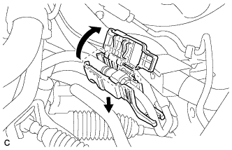
Disengage the claw and remove the No. 1 fuel pipe clamp.
-
Disconnect the fuel tube sub-assembly from the fuel pipe.
-
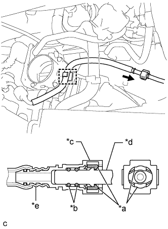
Text in Illustration *a Retainer *b O-ring *c Fuel Tube Connector *d Fuel Pipe *e Nylon Tube 
Pinch 
Pull Pinch the retainer of the fuel tube connector, and then pull the fuel tube connector off of the fuel pipe.
Note
Be sure to disconnect the fuel tube connector by hand.
-
If the fuel tube connector and fuel pipe are stuck, push and pull the fuel tube connector to release it. Pull the fuel tube connector off of the fuel pipe carefully.
Note
-
Be sure to disconnect the fuel tube connector by hand.
-
Do not allow any scratches or foreign matter to get on the parts when disconnecting them as the fuel tube connector has O-rings that seal the fuel pipe.
-
Do not forcibly bend, twist or turn the nylon tube.
-
-
Check if there is any foreign matter on the sealing surfaces of the disconnected fuel lines. Clean them if necessary.
-
Cover the disconnected fuel pipe and fuel tube connector with plastic bags to prevent damage and contamination.
-
-
Disengage the clamp to disconnect the fuel tube sub-assembly from the fuel hose clamp.
-
-
REMOVE FUEL DELIVERY PIPE SUB-ASSEMBLY
-
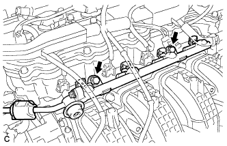
Remove the 2 bolts and fuel delivery pipe sub-assembly with the 4 fuel injector assemblies.
Note
Do not drop the fuel injector assemblies when removing the fuel delivery pipe sub-assembly.
-
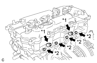
Text in Illustration *1 Fuel Delivery Spacer *2 Injector Vibration Insulator Remove the 2 fuel delivery spacers from the cylinder head.
-
Remove the 4 injector vibration insulators from the cylinder head.
-
-
REMOVE INTAKE MANIFOLD
-
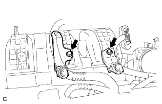
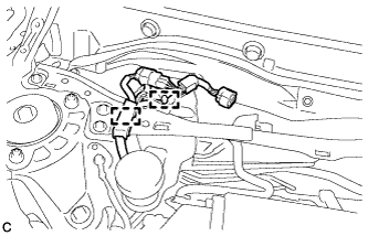
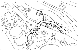
Remove the 2 bolts and 2 wire harness clamp brackets.
-
Disconnect the fuel vapor feed hose.
-
Disconnect the 3 wire harness clamps and connector.
-
Remove the bolt and wire harness clamp bracket.
-
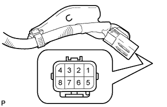
Apply battery voltage to the terminals of the connector to close the tumble control valves (w/ TCV).
Standard Tester Connection Specified Condition Positive (+) battery voltage applied to terminal 8 (M-), and negative (-) battery voltage applied to terminal 4 (M+) Open → Closed Note
-
If this procedure is not performed, the tumble control valves may be damaged when the intake manifold is removed.
-
Apply battery voltage for 1 to 3 seconds.
-
If battery voltage is applied for more than 3 seconds, the actuator may be damaged.
-
Do not allow the lead wires to contact the other terminals.
-
-
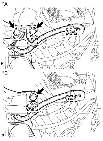
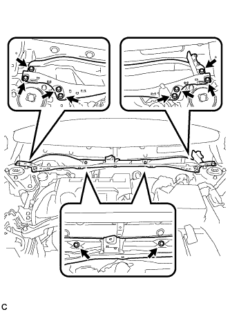
Remove the bolt and separate the wire harness.
-
Disconnect the 2 wire harness clamps and intake air control valve actuator connector (w/ TCV).
-
Disconnect the 2 wire harness clamps (w/o TCV).
Text in Illustration *A w/ TCV *B w/o TCV -
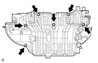
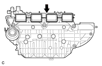
Remove the 6 bolts and intake manifold (w/ TCV).
Note
The tumble control valves may be damaged if they are not closed before removing the intake manifold.
Tech Tips
Connect the battery to the terminals of the actuator to operate the motor and close the valves Click here.
-
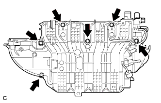
Remove the 6 bolts and intake manifold (w/o TCV).
-
Remove the intake manifold gasket from the intake manifold (w/ TCV).
-
Remove the intake manifold gasket from the intake manifold (w/o TCV).
-
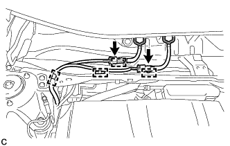
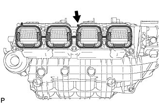
Disconnect the 2 vacuum hoses from the intake manifold and remove the No. 1 check valve.
-
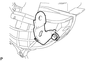
Remove the bolt and wire harness clamp bracket.
-