INSTRUMENT PANEL SAFETY PAD INSTALLATION

-
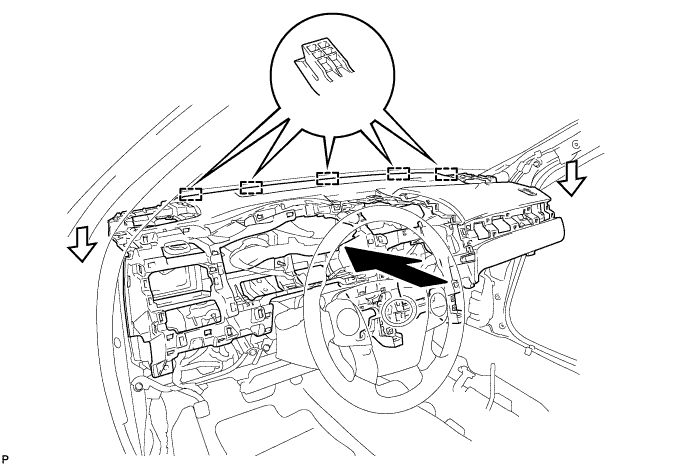
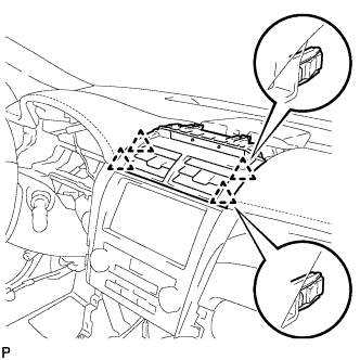
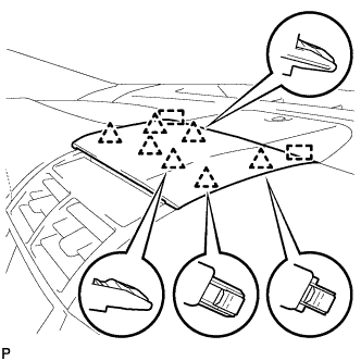
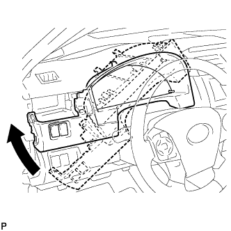
INSTALL INSTRUMENT PANEL SAFETY PAD ASSEMBLY
-
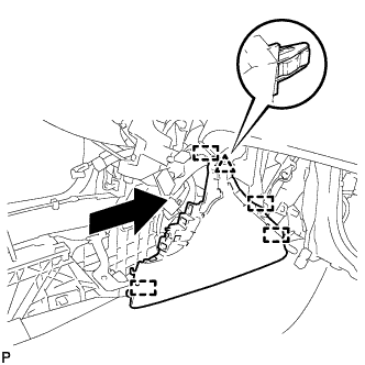
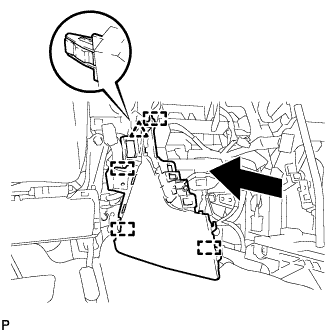
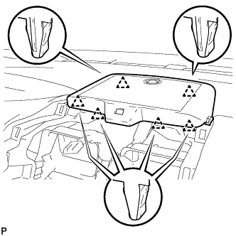
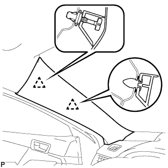
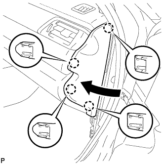
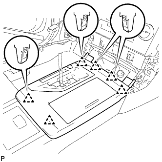
Engage the 5 guides and temporarily install the instrument panel safety pad assembly as shown in the illustration.
Note
-
Do not damage the instrument panel safety pad assembly.
-
Do not allow the wire harnesses to interfere with the surrounding parts.
-
-
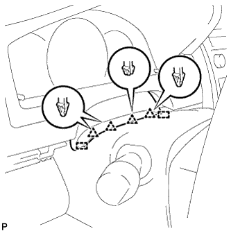
Install the 2 clips.
-
Install the 3 bolts <B> and nut <E> or <F>.
-
Install the 2 passenger airbag bolts <A>.
- Torque:
- 20 N*m { 204 kgf*cm, 15 ft.*lbf }
-
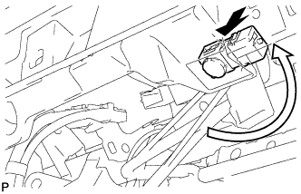
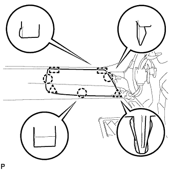
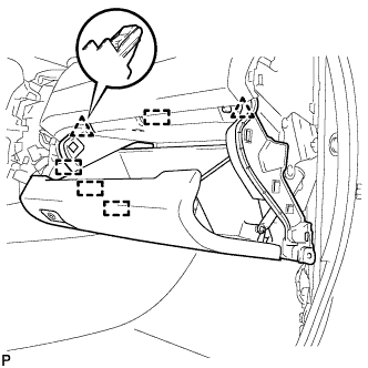
Install the glove box light as shown in the illustration.
-
Engage each clamp.
-
Connect each connector.
-
-
CONNECT NO. 2 INSTRUMENT PANEL WIRE
-
Check that the ignition switch is off.
-
Check that the cable is disconnected from the negative (-) battery terminal.
CAUTION:
Wait at least 90 seconds after disconnecting the cable from the negative (-) battery terminal to disable the SRS system.
-
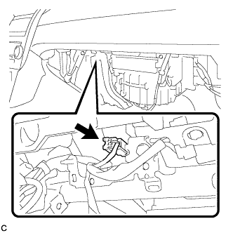
Connect the connector.
Note
When connecting any airbag connector, take care not to damage the airbag wire harness.
-
-
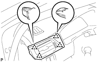
INSTALL NO. 1 INSTRUMENT PANEL GARNISH SUB-ASSEMBLY
-
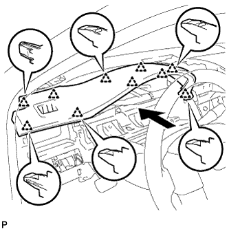
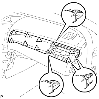
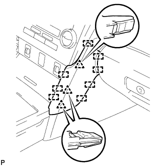
Engage the 10 clips to install the No. 1 instrument panel garnish sub-assembly as shown in the illustration.
-
-
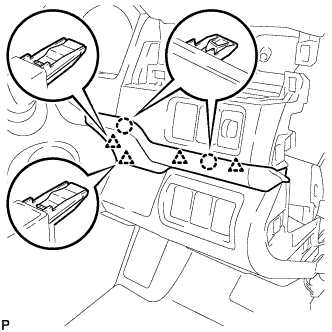
INSTALL LOWER INSTRUMENT PANEL FINISH PANEL ASSEMBLY
-
for LHD with Smart Entry and Start System:
-
Connect the connector.
-
-
Engage the 3 clips and guide to install the lower instrument panel finish panel assembly.
-
-
INSTALL CONSOLE BOX INSERT
-
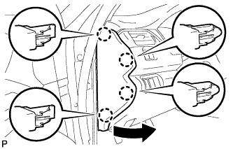
Engage the clip and 4 guides as shown in the illustration.
-
Install the console box insert with the 2 screws <C>.
-
for RHD:
-
Engage the 2 claws to connect the room temperature sensor.
-
-
-
INSTALL FRONT NO. 2 CONSOLE BOX INSERT
-
Engage the clip and 4 guides as shown in the illustration.
-
Install the front No. 2 console box insert with the 2 screws <C>.
-
for LHD:
-
Engage the 2 claws to connect the room temperature sensor.
-
-
-
INSTALL FRONT NO. 2 SPEAKER ASSEMBLY (for RH Side)
Tech Tips
Use the same procedure as for the LH side Click here.
-
INSTALL NO. 2 INSTRUMENT PANEL SPEAKER PANEL SUB-ASSEMBLY
-
Engage the 2 guides.
-
Engage the 3 claws and 2 clips to install the No. 2 instrument panel speaker panel sub-assembly.
-
-
INSTALL FRONT PILLAR GARNISH RH
Tech Tips
Use the same procedure as for the LH side Click here.
-
INSTALL FRONT NO. 3 SPEAKER ASSEMBLY (for 10 Speakers)
-
Connect the connector.
-
Install the front No. 3 speaker assembly with the 2 screws.
Note
Do not touch the speaker cone.
Tech Tips
Install the screws in the order shown in the illustration.
-
-
INSTALL NO. 1 SPEAKER OPENING COVER ASSEMBLY
-
Connect the connector.
-
Engage the 6 clips to install the No. 1 speaker opening cover assembly.
-
-
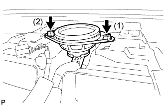
INSTALL FRONT NO. 2 SPEAKER ASSEMBLY (for LH Side)
-
Connect the connector.
-
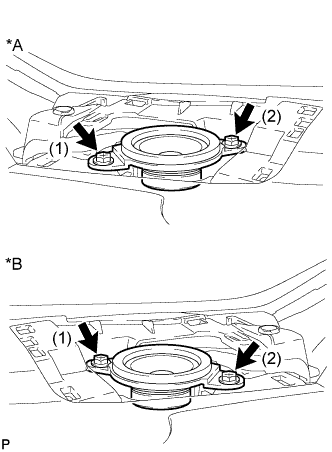
Text in Illustration *A LH Side *B RH Side Install the front No. 2 speaker assembly with the 2 screws.
Note
Do not touch the speaker cone.
Tech Tips
Install the screws in the order shown in the illustration.
-
-
INSTALL NO. 1 INSTRUMENT PANEL SPEAKER PANEL SUB-ASSEMBLY
-
Engage the 2 guides.
-
Engage the 3 claws and 2 clips to install the No. 1 instrument panel speaker panel sub-assembly.
-
-
INSTALL FRONT PILLAR GARNISH LH
-
Remove the protective cover.
-
Make sure that the front pillar garnish clip is not damaged.
Note
If there is any damage, replace the garnish clip with a new one.
-
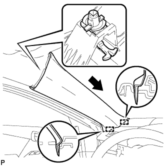
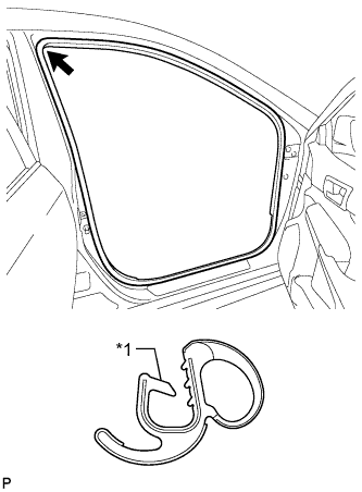
Install the front pillar garnish clip to front pillar garnish LH.
Tech Tips
Install the front pillar garnish clip so that it faces as shown in the illustration.
-
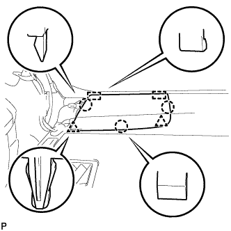
Engage the 2 guides as shown in the illustration.
-
Engage the 2 clips to install the front pillar garnish LH.
-
-
INSTALL NO. 3 INSTRUMENT PANEL REGISTER ASSEMBLY
-
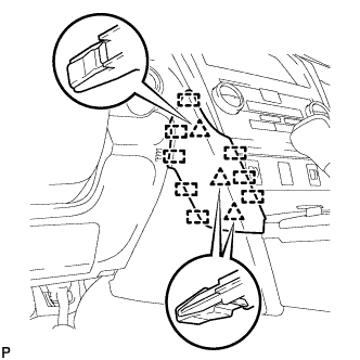
Engage the 10 clips to install the No. 3 instrument panel register assembly.
-
-
INSTALL LOWER INSTRUMENT PANEL SUB-ASSEMBLY
-
Engage the 2 clips and 4 guides.
-
Install the 3 screws <C>.
-
Close the lower instrument panel door.
-
Install the lower instrument panel sub-assembly with the bolt <B> and screws <C>.
-
-
INSTALL NO. 2 INSTRUMENT PANEL UNDER COVER SUB-ASSEMBLY
-
Connect the connector.
-
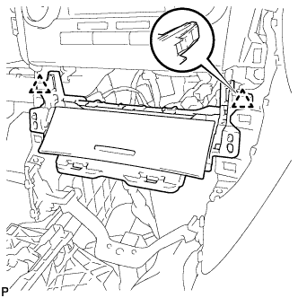
Engage the 2 guides and 4 claws to install the No. 2 instrument panel under cover sub-assembly.
-
-
INSTALL INSTRUMENT SIDE PANEL RH
-
Engage the 3 guides as shown in the illustration.
-
Engage the 4 claws to install the instrument side panel RH as shown in the illustration.
-
-
INSTALL FRONT DOOR OPENING TRIM WEATHERSTRIP RH
-
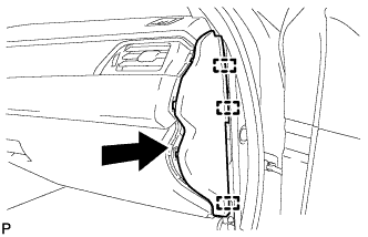
Text in Illustration *1 Alignment Mark (White) Align the alignment mark (White) on the weatherstrip with the protruding portion on the body indicated by the arrow in the illustration, and install the front door opening trim weatherstrip RH.
Note
After installation, check that the corners fit correctly.
-
-
INSTALL COWL SIDE TRIM SUB-ASSEMBLY RH
Tech Tips
Use the same procedure as for the LH side Click here.
-
INSTALL FRONT DOOR SCUFF PLATE RH
Tech Tips
Use the same procedure as for the LH side Click here.
-
INSTALL RADIO RECEIVER ASSEMBLY WITH AIR CONDITIONING CONTROL ASSEMBLY (w/o Navigation System)
-
Connect each connector.
-
Engage the 6 clips to the vehicle body to temporarily install the radio receiver assembly with air conditioning control assembly.
-
Install the radio receiver assembly with air conditioning control assembly with the 4 bolts.
-
-
INSTALL NAVIGATION RECEIVER ASSEMBLY WITH AIR CONDITIONING CONTROL ASSEMBLY (w/ Navigation System)
-
Connect each connector.
-
Engage the 6 clips to the vehicle body to temporarily install the navigation receiver assembly with air conditioning control assembly.
-
Install the navigation receiver assembly with air conditioning control assembly with the 4 bolts.
-
-
INSTALL FRONT ASH RECEPTACLE ASSEMBLY
-
Connect each connector.
-
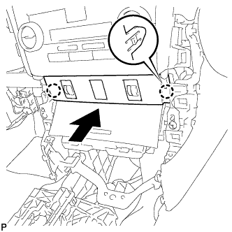
Engage the 2 clips.
-
Install the front ash receptacle assembly with the 2 screws <C>.
-
-
INSTALL FRONT CONSOLE UPPER PANEL GARNISH
-
for Blank Type:
-

Engage the 2 claws to install the front console upper panel garnish as shown in the illustration.
-
-
for 3 Switch Hole Type:
-
Connect each connector.
-
Engage the 2 claws to install the front console upper panel garnish as shown in the illustration.
-
-
-
INSTALL NO. 2 INSTRUMENT PANEL REGISTER ASSEMBLY
-
Connect the connector.
-
Engage the 4 clips to install the No. 2 instrument panel register assembly.
Note
When installing the No. 2 instrument panel register assembly, check that the wire harness is not caught between the No. 2 instrument panel register assembly and duct.
-
-
INSTALL CENTER INSTRUMENT CLUSTER FINISH PANEL SUB-ASSEMBLY
-
Engage the 7 clips and 2 guides to install the center instrument cluster finish panel sub-assembly.
-
-
INSTALL CONSOLE BOX ASSEMBLY
-
Engage the 4 guides as shown in the illustration.
-
Install the console box assembly with the 2 bolts and 2 screws.
-
-
INSTALL CONSOLE BOX CARPET
-
Install the console box carpet.
-
-
INSTALL NO. 4 CONSOLE BOX DUCT
-
Engage the claw to install the No. 4 console box duct.
-
-
INSTALL UPPER CONSOLE BOX SUB-ASSEMBLY
-
Connect the 2 connectors.
-
Engage the clamp.
-
Engage the 2 guides and 4 clips as shown in the illustration.
-
Install the upper console box sub-assembly with the 2 screws.
-
-
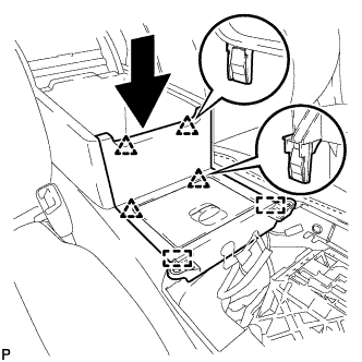
INSTALL REAR CONSOLE UPPER PANEL SUB-ASSEMBLY
-
Connect each connector.
-
Engage the 6 clips to install the rear console upper panel sub-assembly.
-
Move the shift lever to P.
-
-
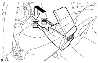
INSTALL SHIFT LEVER KNOB SUB-ASSEMBLY
-
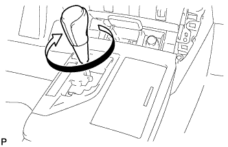
Turn the shift lever knob sub-assembly clockwise to install the shift lever knob sub-assembly.
-
-
INSTALL FRONT PANEL GARNISH RH
-
Engage the 3 clips and 8 guides to install the front panel garnish RH.
-
-
INSTALL INSTRUMENT PANEL SUB-ASSEMBLY
-
w/o Driver Side Knee Airbag:
-
Engage the 5 clips and 3 guides.
-
-
w/ Driver Side Knee Airbag:
-
Engage the 4 claws, 7 clips and 3 guides.
-
-
Install the instrument panel sub-assembly with the 2 bolts <B>.
-
-
CONNECT HOOD LOCK CONTROL LEVER SUB-ASSEMBLY
-
Engage the claw and 2 guides to connect the hood lock control lever sub-assembly.
-
-
INSTALL FRONT PANEL GARNISH LH
-
Engage the 3 clips and 8 guides to install the front panel garnish LH.
-
-
INSTALL COMBINATION METER ASSEMBLY
-
Connect the 2 connectors.
-
Engage the wire harness clamp.
-
Install the combination meter assembly with the 4 screws.
-
-
INSTALL INSTRUMENT CLUSTER FINISH PANEL ASSEMBLY
-
Temporarily install the instrument cluster finish panel assembly as shown in the illustration.
-
Connect each connector.
-
for LHD:
-
Engage the 3 claws, 7 clips and 4 guides.
-
-
for RHD:
-
Engage the 4 claws, 5 clips and 4 guides.
-
-
Engage the 4 clips and 2 guides to install the instrument cluster finish panel assembly.
-
-
INSTALL NO. 1 INSTRUMENT PANEL REGISTER ASSEMBLY
-
Engage the 4 clips to install the No. 1 instrument panel register assembly.
-
-
INSTALL UPPER INSTRUMENT PANEL FINISH PANEL (for RHD)
-
w/ Smart Entry and Start System:
-
Connect the connector.
-
-
Engage the 2 claws and 4 clips to install the upper instrument panel finish panel.
-
-
INSTALL INSTRUMENT SIDE PANEL LH
-
Engage the 3 guides.
-
Engage the 4 claws to install the instrument side panel LH as shown in the illustration.
-
-
INSTALL FRONT DOOR OPENING TRIM WEATHERSTRIP LH
-
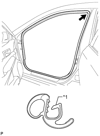
Text in Illustration *1 Alignment Mark (Yellow) Align the alignment mark (Yellow) on the weatherstrip with the protruding portion on the body indicated by the arrow in the illustration, and install the front door opening trim weatherstrip LH.
Note
After installation, check that the corners fit correctly.
-
-
INSTALL COWL SIDE TRIM SUB-ASSEMBLY LH
-
Engage the 2 clips.
-
Install the cowl side trim sub-assembly LH with the clip.
-
-
INSTALL FRONT DOOR SCUFF PLATE LH
-
Engage the 10 claws to install the front door scuff plate LH.
-
-
CONNECT CABLE TO NEGATIVE BATTERY TERMINAL (for Manual Tilt and Manual Telescopic Steering Column)
Note
When disconnecting the cable, some systems need to be initialized after the cable is reconnected Click here.
-
CONNECT CABLE TO NEGATIVE BATTERY TERMINAL (for Power Tilt and Power Telescopic Steering Column)
Note
-
Reset the auto away/return function setting to the previous condition by changing the customize parameter Click here.
-
When disconnecting the cable, some systems need to be initialized after the cable is reconnected Click here.
-
-
INSPECT SRS WARNING LIGHT