AIR CONDITIONING UNIT DISASSEMBLY

-
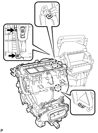
REMOVE NO. 1 AIR DUCT SUB-ASSEMBLY
-
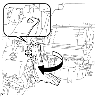
Disengage the 2 claws and guide, and remove the No. 1 air duct sub-assembly as shown in the illustration.
-
-
REMOVE NO. 6 HEATER TO REGISTER DUCT ASSEMBLY
-
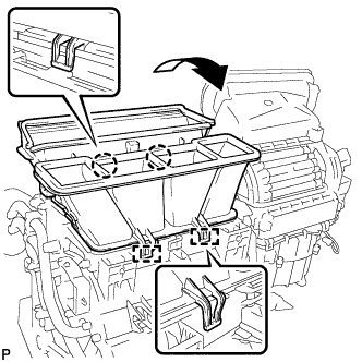
Disengage the 2 claws and 2 guides, and remove the No. 6 heater to register duct assembly as shown in the illustration.
-
-
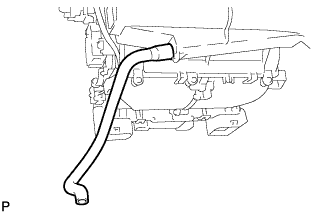
REMOVE COOLER THERMISTOR HOSE
-
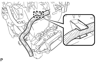
Disengage the clamp and remove the cooler thermistor hose.
-
-
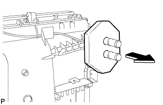
REMOVE ASPIRATOR
-
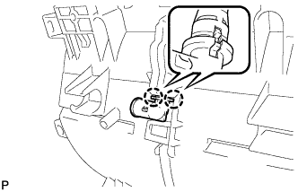
Disengage the 2 claws and remove the aspirator.
-
-
REMOVE AIR CONDITIONING HARNESS ASSEMBLY (for Dual Type)
-
Remove the heater packing as shown in the illustration.
-
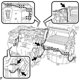
Disconnect the 5 connectors.
-
Disengage 7 clamps and remove the air conditioning harness assembly.
-
-
REMOVE AIR CONDITIONING HARNESS ASSEMBLY (for 3 Zone Type)
-
Remove the heater packing as shown in the illustration.
-
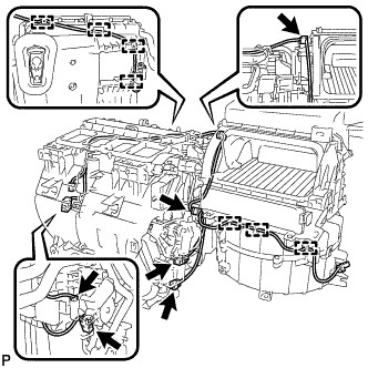
Disconnect the 6 connectors.
-
Disengage 7 clamps and remove the air conditioning harness assembly.
-
-
REMOVE COOLER EXPANSION VALVE
-
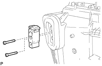
Using a 4 mm hexagon wrench, remove the 2 hexagon bolts and cooler expansion valve.
-
-
REMOVE AIR CONDITIONING RADIATOR ASSEMBLY
-
Remove the 2 screws.
-
Disengage the 2 claws and remove the air conditioning radiator assembly.
-
-
REMOVE DRAIN COOLER HOSE
-
Remove the drain cooler hose from the air conditioning radiator assembly.
-
-
REMOVE NO. 1 AIR CONDITIONING RADIATOR DAMPER SERVO SUB-ASSEMBLY
-
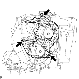
Remove the 3 screws and No. 1 air conditioning radiator damper servo sub-assembly.
-
-
REMOVE NO. 2 AIR CONDITIONING RADIATOR DAMPER SERVO SUB-ASSEMBLY
-
Remove the 2 screws and No. 2 air conditioning radiator damper servo sub-assembly.
-
-
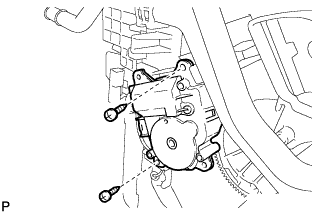
REMOVE NO. 3 AIR CONDITIONING RADIATOR DAMPER SERVO SUB-ASSEMBLY (for 3 Zone Type)
-
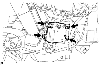
Remove the 4 screws and No. 3 air conditioning radiator damper servo sub-assembly.
-
-
REMOVE HEATER RADIATOR UNIT SUB-ASSEMBLY
-
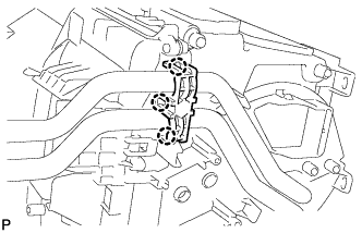
Disengage the 3 claws and remove the heater clamp.
-
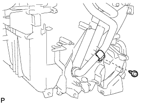
Remove the screw and clamp.
-
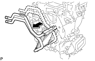
Remove the heater radiator unit sub-assembly from the air conditioning radiator assembly as shown in the illustration.
Note
Prepare a drain pan or cloth in case the coolant leaks.
-
-
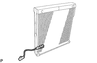
REMOVE NO. 1 COOLER EVAPORATOR SUB-ASSEMBLY
-
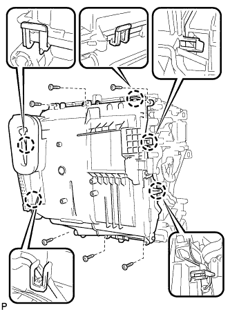
Remove the 6 screws.
-
Disengage the 5 claws and remove the plate cover.
-
Disengage the clamp and remove the No. 1 cooler evaporator sub-assembly with the No. 1 cooler thermistor.
-
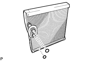
Remove the 2 O-rings from the No. 1 cooler evaporator sub-assembly.
-
-
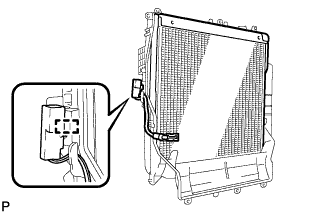
REMOVE NO. 1 COOLER THERMISTOR
-
Remove the No. 1 cooler thermistor.
-