OUTER REAR VIEW MIRROR DISASSEMBLY

Tech Tips
-
Use the same procedure for both the RH and LH sides.
-
The procedure described below is for the LH side.
-
REMOVE OUTER MIRROR
-
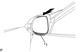
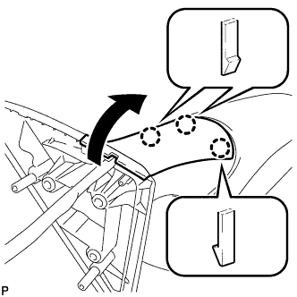
Text in Illustration *1 Protective Tape Apply protective tape to the area shown in the illustration.
-
Push the upper part of the mirror surface and tilt it.
-
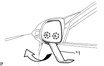
Text in Illustration *1 Moulding Remover Using a moulding remover, disengage the 2 claws at the lower part of the outer mirror as shown in the illustration.
-
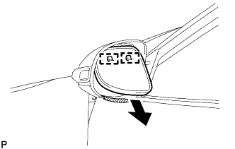
Disengage the 2 guides as shown in the illustration.
-
Disconnect the 2 connectors and remove the outer mirror.
-
-
REMOVE OUTER MIRROR COVER
-
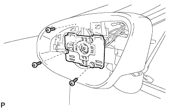
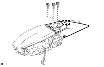
Remove the 3 screws.
-
Disengage the clamp.
-
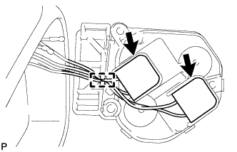
Disconnect the 2 connectors and remove the mirror actuator.
-
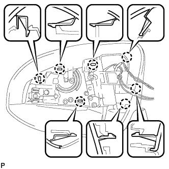
Disengage the 7 claws and remove the outer mirror cover.
-
-
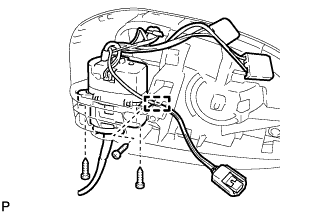
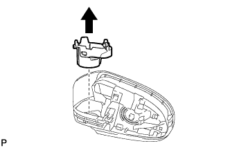
REMOVE SIDE TURN SIGNAL LIGHT ASSEMBLY
-
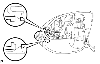
Disengage the 2 claws.
-
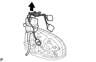
Disconnect the connector and remove the side turn signal light assembly.
-
-
REMOVE OUTER MIRROR RETRACTOR (for TMC Made)
-
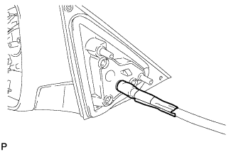
Remove the vinyl tape.
-
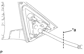
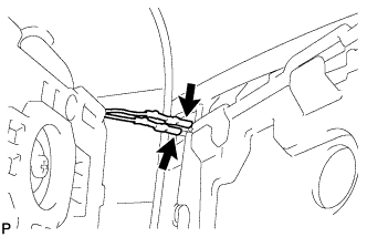
Text in Illustration *a Cut Cut the wire harness at the position shown in the illustration.
Note
Make sure to replace the wire harness with a new one.
-
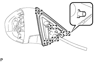
Disengage the 5 pins and remove the gasket.
Note
Make sure to replace the gasket with a new one.
-
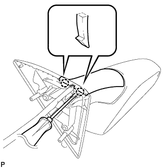
Using a screwdriver, disengage the 2 claws.
-
Disengage the 3 claws and remove the lower cover as shown in the illustration.
Note
Make sure to replace the lower cover with a new one.
-
Disengage the clamp.
-
Using a T25 "TORX" socket wrench, remove the 3 screws and base.
Note
Make sure to replace the "TORX" screws with new ones.
-
Disengage the clamp.
-
Remove the 3 screws.
-
Remove the frame sub-assembly and wire harness as shown in the illustration.
Note
Make sure to replace the frame sub-assembly wire harness with a new one.
-
Remove the support as shown in the illustration.
Note
Make sure to replace the support with a new one.
-