CYLINDER BLOCK DISASSEMBLY

-
INSPECT CONNECTING ROD THRUST CLEARANCE
-
Install the connecting rod cap Click here.
-
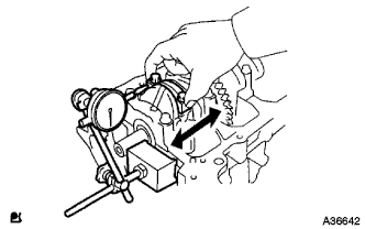
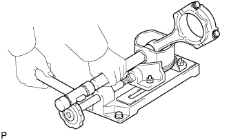
Using a dial indicator, measure the thrust clearance while moving the connecting rod back and forth.
Standard thrust clearance 0.160 to 0.362 mm (0.00630 to 0.0143 in.) Maximum thrust clearance 0.362 mm (0.0143 in.) If the thrust clearance is greater than the maximum, replace the connecting rod assemblies as necessary. If necessary, replace the crankshaft.
-
-
INSPECT CONNECTING ROD OIL CLEARANCE
-
Clean the crank pin and bearing.
-
Check the crank pin and bearing for pitting and scratches.
-
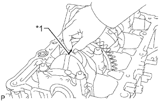
Text in Illustration *1 Plastigage Lay a strip of Plastigage on the crank pin.
-
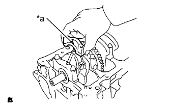
Text in Illustration *a Front Mark Check that the front mark of the connecting rod cap is facing forward.
-
Install the connecting rod cap Click here.
Note
Do not turn the crankshaft.
-
Remove the 2 bolts and connecting rod cap Click here.
-
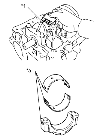
Text in Illustration *1 Plastigage *a 1, 2, or 3 Mark Measure the Plastigage at its widest point.
Standard oil clearance 0.024 to 0.048 mm (0.000945 to 0.00189 in.) Maximum oil clearance 0.08 mm (0.00315 in.) Note
Completely remove the Plastigage after the measurement.
If the oil clearance is greater than the maximum, replace the connecting rod bearings. If necessary, inspect the crankshaft.
Tech Tips
If replacing a crankshaft bearing, replace it with one that has the same number as its respective connecting rod cap. Each bearing's standard thickness is indicated by a 1, 2, or 3 mark on its surface.
Standard Connecting Rod Large End Bore Diameter Mark Specified Condition Mark 1 51.000 to 51.007 mm (2.0079 to 2.0082 in.) Mark 2 51.008 to 51.013 mm (2.0082 to 2.0084 in.) Mark 3 51.014 to 51.020 mm (2.0084 to 2.0087 in.) Standard Connecting Rod Bearing Thickness Mark Specified Condition Mark 1 1.485 to 1.488 mm (0.0585 to 0.0586 in.) Mark 2 1.489 to 1.491 mm (0.0586 to 0.0587 in.) Mark 3 1.492 to 1.494 mm (0.0587 to 0.0588 in.) Standard crankshaft pin diameter 47.990 to 48.000 (1.8894 to 1.8898 in.)
-
-
REMOVE PISTON SUB-ASSEMBLY WITH CONNECTING ROD
-
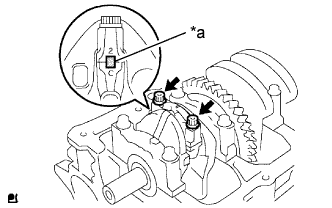
Text in Illustration *a Matchmark Check that the matchmarks on the connecting rod and connecting rod cap are aligned to ensure the correct reassembly.
Tech Tips
The matchmarks on the connecting rods and connecting rod caps are provided for ensuring the correct reassembly.
-
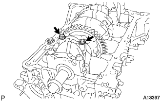
Using a 12 mm socket wrench, uniformly loosen and remove the 2 bolts.
-
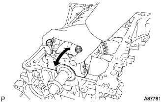
Using the 2 removed connecting rod cap bolts, remove the connecting rod cap and No. 2 crankshaft bearing by wiggling the connecting rod cap right and left.
Tech Tips
Keep the No. 2 crankshaft bearing inserted in the connecting rod cap.
-
Push the piston, connecting rod assembly and No. 1 crankshaft bearing through the top of the cylinder block.
Tech Tips
-
Keep the No. 2 crankshaft bearing, connecting rod and connecting rod cap together.
-
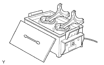
Arrange the piston and connecting rod assemblies in the correct order.
-
-
-
REMOVE CONNECTING ROD BEARING
-
Remove the connecting rod bearings.
Tech Tips
Arrange the removed parts in the correct order.
-
-
REMOVE PISTON RING SET
-
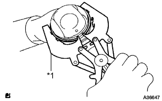
Text in Illustration *1 Piston Ring Expander Using a piston ring expander, remove the 2 compression rings.
-
Remove the 2 oil ring side rails and oil ring expander by hand.
Tech Tips
Arrange the removed parts in the correct order.
-
-
REMOVE PISTON PIN HOLE SNAP RING
-
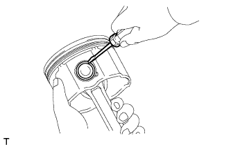
Using a screwdriver, pry out the 2 piston pin hole snap rings.
-
-
REMOVE PISTON
-
Gradually heat the pistons to between 80 and 90°C (176 and 194°F).
-
Using a plastic hammer and brass bar, lightly tap out the piston pin and remove the connecting rod.
Tech Tips
-
The piston and pin are a matched set.
-
Arrange the pistons, pins, rings, connecting rods and bearings in the correct order.
-
-
-
INSPECT CRANKSHAFT THRUST CLEARANCE
-
Install the crankshaft bearing cap Click here.
-
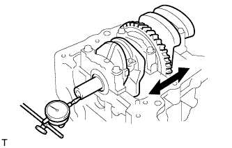
Using a dial indicator, measure the thrust clearance while prying the crankshaft back and forth with a screwdriver.
Standard thrust clearance 0.04 to 0.24 mm (0.00157 to 0.00945 in.) Maximum thrust clearance 0.30 mm (0.0118 in.) If the crankshaft thrust clearance is greater than the maximum, replace the crankshaft thrust washers as a set.
Tech Tips
The thrust washer thickness is 1.93 to 1.98 mm (0.0760 to 0.0780 in.).
-
-
REMOVE CRANKSHAFT
-
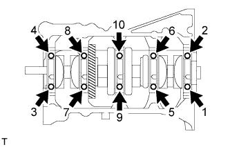
Uniformly loosen and remove the 10 crankshaft bearing cap set bolts in the sequence shown in the illustration.
-
Use 2 removed bearing cap set bolts to remove the 5 crankshaft bearing caps and 5 No. 2 crankshaft bearings.
Note
Insert the bolts into one of the crankshaft bearing caps. Ease the crankshaft bearing cap out by gently pulling up and applying force toward the front and back sides of the cylinder block, as shown in the illustration. Take care not to damage the contact surfaces of the crankshaft bearing cap and cylinder block.
Tech Tips
-
Keep the No. 2 crankshaft bearing and crankshaft bearing cap.
-
Arrange the crankshaft bearing caps in the correct order.
-
-
Lift out the crankshaft.
-
-
REMOVE UPPER CRANKSHAFT THRUST WASHER
-
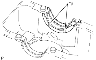
Text in Illustration *a Oil Groove Remove the upper crankshaft thrust washers from the cylinder block.
-
-
REMOVE CRANKSHAFT BEARING
-
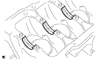
Remove the 5 crankshaft bearings from the cylinder block.
Tech Tips
Arrange the removed parts in the correct order.
-
-
REMOVE NO. 2 CRANKSHAFT BEARING
-
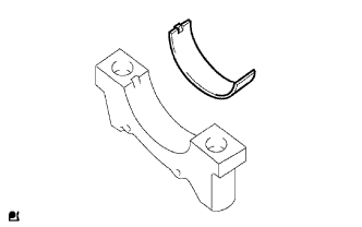
Remove the 5 No. 2 crankshaft bearings from the 5 crankshaft bearing caps.
Tech Tips
Arrange the removed parts in the correct order.
-
-
REMOVE STUD BOLT
-
REMOVE RING PIN
-
REMOVE STRAIGHT PIN