CYLINDER HEAD INSPECTION

-
INSPECT CYLINDER HEAD FOR WARPAGE
-
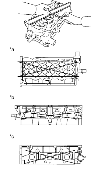
Text in Illustration *a Cylinder Block Side *b Intake Manifold Side *c Exhaust Manifold Side Using a precision straight edge and a feeler gauge, measure the surface contacting the cylinder block and the manifolds for warpage.
Maximum Warpage Item Specified Condition Cylinder block side 0.08 mm (0.00315 in.) Intake manifold side 0.08 mm (0.00315 in.) Exhaust manifold side 0.08 mm (0.00315 in.) If the warpage is greater than the maximum, replace the cylinder head.
-
-
INSPECT CYLINDER HEAD FOR CRACKS
-
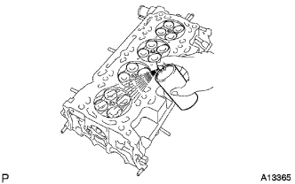
Using a dye penetrant, check the intake ports, exhaust ports and cylinder surface for cracks.
If cracked, replace the cylinder head.
-
-
INSPECT CAMSHAFT THRUST CLEARANCE
-
Install the camshafts Click here.
-
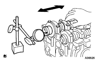
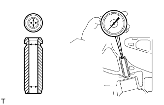
Using a dial indicator, measure the thrust clearance while moving the camshaft back and forth.
Standard Thrust Clearance Item Specified Condition Intake 0.040 to 0.095 mm (0.00157 to 0.00374 in.) Exhaust 0.080 to 0.135 mm (0.00315 to 0.00532 in.) Maximum Thrust Clearance Item Specified Condition Intake 0.110 mm (0.00433 in.) Exhaust 0.150 mm (0.00591 in.) If the thrust clearance is greater than the maximum, replace the cylinder head. If the thrust surface is damaged, replace the camshaft.
-
-
INSPECT CAMSHAFT OIL CLEARANCE
-
Clean the bearing caps and camshaft journals.
-
Place the camshafts on the cylinder head.
-
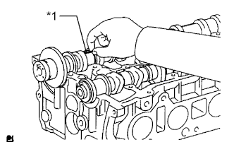
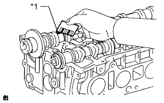
Text in Illustration *1 Plastigage Lay a strip of Plastigage across each of the camshaft journals.
-
Install the bearing caps Click here.
Note
Do not turn the camshaft.
-
Remove the bearing caps Click here.
-
Text in Illustration *1 Plastigage Measure the Plastigage at its widest point.
Standard Oil Clearance Item Specified Condition Intake No. 1 journal 0.007 to 0.038 mm (0.000276 to 0.00150 in.) Exhaust No. 1 journal 0.040 to 0.079 mm (0.00157 to 0.00311 in.) Other journals 0.025 to 0.062 mm (0.000984 to 0.00244 in.) Maximum Oil Clearance Item Specified Condition Intake No. 1 journal 0.070 mm (0.00276 in.) Other journals 0.100 mm (0.00394 in.) Note
Completely remove the Plastigage after the inspection.
-
If the oil clearance is greater than the maximum, replace the camshaft. If necessary, replace the cylinder head.
-
If the oil clearance on the camshaft No. 1 journal is greater than the maximum, choose a new bearing and install it.
-
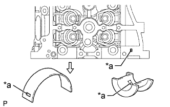
Text in Illustration *a Number Mark Check the number mark shown in the illustration.
Cylinder Head Journal Bore Diameter Mark 1 Mark 2 Mark 3 40.000 to 40.009 mm (1.5748 to 1.5752 in.) 40.010 to 40.017 mm (1.5752 to 1.5755 in.) 40.018 to 40.025 mm (1.5755 to 1.5758 in.) Standard Bearing Center Wall Thickness Mark 1 Mark 2 Mark 3 2.000 to 2.004 mm (0.0787 to 0.0789 in.) 2.005 to 2.008 mm (0.0789 to 0.0791 in.) 2.009 to 2.012 mm (0.0791 to 0.0792 in.) Camshaft journal diameter 35.971 to 35.985 mm (1.4162 to 1.4167 in.)
-
-
-
INSPECT INNER COMPRESSION SPRING
-
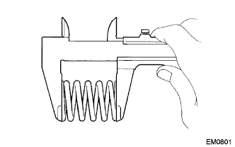
Using a vernier caliper, measure the free length of the inner compression spring.
Free length 47.43 mm (1.867 in.) If the free length is not as specified, replace the inner compression spring.
-
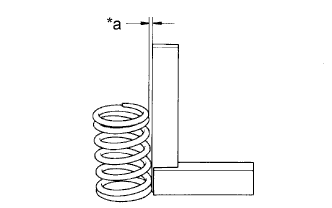
Text in Illustration *a Deviation Using a steel set square, measure the deviation of the inner compression spring.
Maximum deviation 1.6 mm (0.0630 in.) If the deviation is greater than the maximum, replace the inner compression spring.
-
-
INSPECT INTAKE VALVE
-
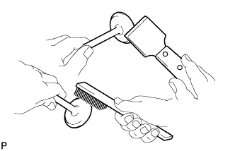
Using a gasket scraper, scrape off any carbon on the valve head.
-
Using a wire brush, thoroughly clean the intake valve.
-
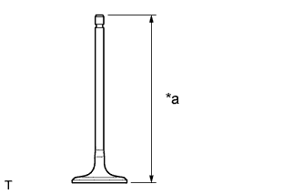
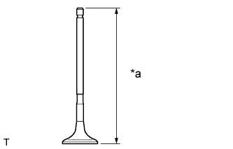
Text in Illustration *a Overall Length Using a vernier caliper, measure the overall length of the intake valve.
Standard overall length 101.71 mm (4.0043 in.) Minimum overall length 101.21 mm (3.9846 in.) If the overall length is less than the minimum, replace the intake valve.
-
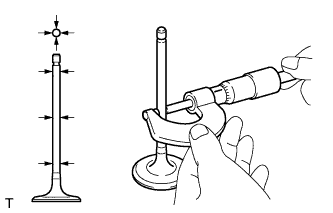
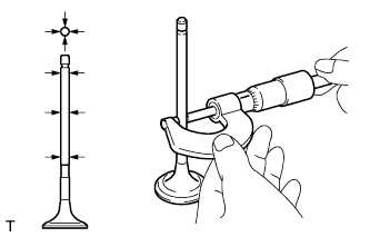
Using a micrometer, measure the diameter of the valve stem.
Standard valve stem diameter 5.470 to 5.485 mm (0.2154 to 0.2159 in.) If the valve stem is not as specified, check the oil clearance.
-
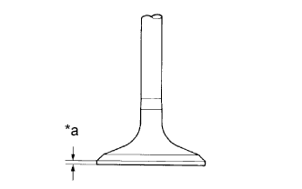
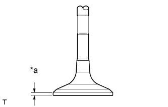
Text in Illustration *a Margin Thickness Using a vernier caliper, measure the valve head margin thickness.
Standard margin thickness 1.05 to 1.45 mm (0.0413 to 0.0571 in.) Minimum margin thickness 0.50 mm (0.0197 in.) If the margin thickness is less than the minimum, replace the intake valve.
-
-
INSPECT EXHAUST VALVE
-
Using a gasket scraper, scrape off any carbon on the valve head.
-
Using a wire brush, thoroughly clean the exhaust valve.
-
Text in Illustration *a Overall Length Using a vernier caliper, measure the overall length of the exhaust valve.
Standard overall length 101.15 mm (3.9823 in.) Minimum overall length 100.70 mm (3.9646 in.) If the overall length is less than the minimum, replace the exhaust valve.
-
Using a micrometer, measure the diameter of the valve stem.
Standard valve stem diameter 5.465 to 5.480 mm (0.2152 to 0.2157 in.) If the valve stem is not as specified, check the oil clearance.
-
Text in Illustration *a Margin Thickness Using a vernier caliper, measure the valve head margin thickness.
Standard margin thickness 1.20 to 1.60 mm (0.0472 to 0.0630 in.) Minimum margin thickness 0.50 mm (0.0197 in.) If the margin thickness is less than the minimum, replace the exhaust valve.
-
-
INSPECT INTAKE VALVE GUIDE BUSH
-
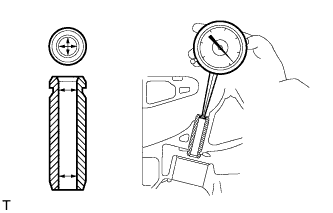
Using a caliper gauge, measure the inside diameter of the intake valve guide bush.
Standard bushing inside diameter 5.510 to 5.530 mm (0.2169 to 0.2177 in.) -
Subtract the valve stem diameter measurement from the intake valve guide bush inside diameter measurement.
Standard oil clearance 0.025 to 0.060 mm (0.000984 to 0.00236 in.) Maximum oil clearance 0.080 mm (0.00315 in.) If the clearance is greater than the maximum, replace the intake valve and intake valve guide bush.
-
-
INSPECT EXHAUST VALVE GUIDE BUSH
-
Using a caliper gauge, measure the inside diameter of the exhaust valve guide bush.
Standard bushing inside diameter 5.510 to 5.530 mm (0.2169 to 0.2177 in.) -
Subtract the valve stem diameter measurement from the guide bushing inside diameter measurement.
Standard oil clearance 0.030 to 0.065 mm (0.00118 to 0.00256 in.) Maximum oil clearance 0.10 mm (0.00394 in.) If the clearance is greater than the maximum, replace the exhaust valve and exhaust valve guide bush.
-
-
INSPECT VALVE LIFTER
-
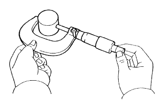
Using a micrometer, measure the lifter diameter.
Standard lifter diameter 30.966 to 30.976 mm (1.2191 to 1.2195 in.) -
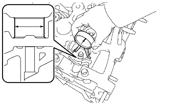
Using a caliper gauge, measure the lifter bore diameter of the cylinder head.
Standard lifter bore diameter 31.009 to 31.025 mm (1.2208 to 1.2215 in.) -
Subtract the lifter diameter measurement from the lifter bore diameter measurement.
Standard oil clearance 0.033 to 0.059 mm (0.00130 to 0.00232 in.) Maximum oil clearance 0.070 mm (0.00276 in.) If the oil clearance is greater than the maximum, replace the lifter. If necessary, replace the cylinder head.
-
-
INSPECT CYLINDER HEAD SET BOLT
-
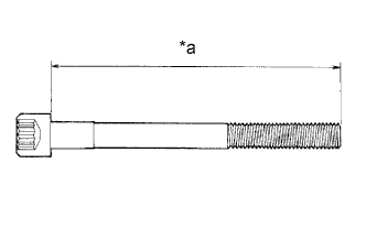
Text in Illustration *a Measurement Length Using a vernier caliper, measure the length of the cylinder head set bolts from the seat to the end.
Standard bolt length 141.3 to 142.7 mm (5.563 to 5.618 in.) Maximum bolt length 144.2 mm (5.677 in.) If the cylinder head set bolt length is greater than the maximum, replace the cylinder head set bolt.
-