ENGINE UNIT INSTALLATION

-
INSTALL RADIO SETTING CONDENSER
-
Install the radio setting condenser with the bolt.
- Torque:
- 10 N*m { 102 kgf*cm, 7 ft.*lbf }
-
-
INSTALL ENGINE COOLANT TEMPERATURE SENSOR
-
Install a new gasket to the engine coolant temperature sensor.
-
Using a 19 mm ball joint lock nut wrench, install the engine coolant temperature sensor.
- Torque:
- 20 N*m { 204 kgf*cm, 15 ft.*lbf }
Note
Use the torque value compensation formula to calculate the torque value for use when a torque wrench is combined with a tool such as a ball joint lock nut wrench Click here.
-
Connect the engine coolant temperature sensor connector.
-
-
INSTALL ENGINE OIL PRESSURE SWITCH ASSEMBLY
-
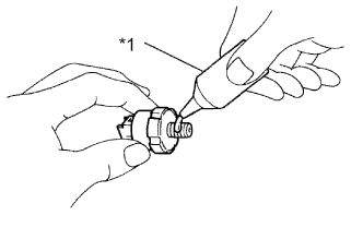
Text in Illustration *1 Adhesive Apply adhesive to 2 or 3 threads of the engine oil pressure switch assembly.
Adhesive Toyota Genuine Adhesive 1344, Three Bond 1344 or equivalent -
Using a 24 mm deep socket wrench, install the engine oil pressure switch assembly.
- Torque:
- 15 N*m { 153 kgf*cm, 11 ft.*lbf }
Note
Do not start the engine within 1 hour of installation.
-
Connect the engine oil pressure switch connector.
-
-
INSTALL KNOCK CONTROL SENSOR
-
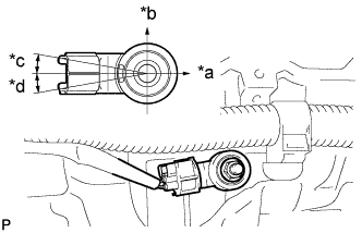
Text in Illustration *a Front of Engine *b Up *c 10° *d 10° Install the knock control sensor with the bolt so that the knock control sensor is positioned as shown in the illustration.
- Torque:
- 20 N*m { 204 kgf*cm, 15 ft.*lbf }
Note
The acceptable installation angle of the knock control sensor is between 10° upward and 10° downward from the horizontal position.
-
Connect the knock control sensor connector.
-
-
INSTALL IGNITION COIL ASSEMBLY
-
Install the 4 ignition coil assemblies with the 4 bolts.
- Torque:
- 9.0 N*m { 92 kgf*cm, 80 in.*lbf }
-
Connect the 4 ignition coil assembly connectors.
-
-
INSTALL NO. 1 WATER BY-PASS PIPE
-
Install a new water by-pass pipe gasket and the No. 1 water by-pass pipe with the bolt and 2 nuts.
- Torque:
- 9.0 N*m { 92 kgf*cm, 80 in.*lbf }
-
-
INSTALL ENGINE OIL LEVEL DIPSTICK GUIDE
-
Install a new engine oil level dipstick guide O-ring and the engine oil level dipstick guide with the bolt.
- Torque:
- 9.0 N*m { 92 kgf*cm, 80 in.*lbf }
-
-
INSTALL ENGINE OIL LEVEL DIPSTICK
-
Install the engine oil level dipstick.
-
-
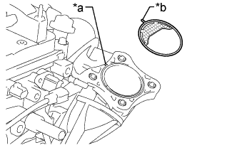
INSTALL THERMOSTAT
-
Install a new gasket to the thermostat.
-
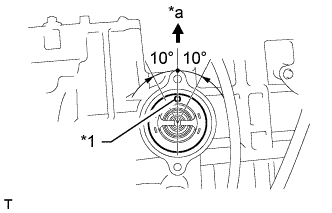
Text in Illustration *1 Jiggle Valve *a Upward Install the thermostat with the jiggle valve facing upward.
Tech Tips
The jiggle valve may be set to within 10° on either side of the indicated position.
-
-
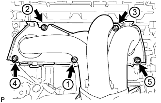
INSTALL WATER INLET
-
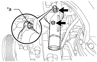
Text in Illustration *a Mark Install the water inlet with the mark upward.
-
Install the water inlet with the 2 nuts.
- Torque:
- 9.0 N*m { 92 kgf*cm, 80 in.*lbf }
-
-
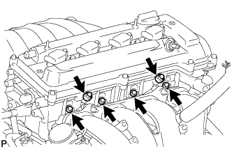
INSTALL EXHAUST MANIFOLD CONVERTER SUB-ASSEMBLY
-
Set a new gasket to the cylinder head sub-assembly.
-
Temporarily install the exhaust manifold converter sub-assembly with the 5 nuts.
-
Temporarily install the No. 2 manifold stay and manifold stay with the 2 bolts and 2 nuts.
-
Using a 12 mm deep socket wrench, install the exhaust manifold converter sub-assembly and 5 nuts in the order shown in the illustration.
- Torque:
- 37 N*m { 377 kgf*cm, 27 ft.*lbf }
-
Connect the air fuel ratio sensor connector.
-
-
INSTALL NO. 2 MANIFOLD STAY
-
Install the No. 2 manifold stay with the bolt and nut.
- Torque:
- 44 N*m { 449 kgf*cm, 32 ft.*lbf }
-
-
INSTALL MANIFOLD STAY
-
Install the manifold stay with the bolt and nut.
- Torque:
- 44 N*m { 449 kgf*cm, 32 ft.*lbf }
-
-
INSTALL NO. 1 EXHAUST MANIFOLD HEAT INSULATOR
-
Install the No. 1 exhaust manifold heat insulator with the 4 bolts.
- Torque:
- 12 N*m { 122 kgf*cm, 9 ft.*lbf }
-
-
INSTALL NO. 1 INTAKE MANIFOLD INSULATOR
-
Install the No. 1 intake manifold insulator to the cylinder block.
-
-
INSTALL INTAKE MANIFOLD
-
Install the vacuum hose clamp with the bolt.
- Torque:
- 5.4 N*m { 55 kgf*cm, 48 in.*lbf }
-
Install a new No. 1 intake manifold to head gasket to the intake manifold.
-
Set the intake manifold on the engine assembly.
-
Using an E7 "TORX" wrench, install the 2 stud bolts.
- Torque:
- 9.5 N*m { 97 kgf*cm, 84 in.*lbf }
-
Temporarily install the intake manifold with the 5 bolts and 2 nuts.
-
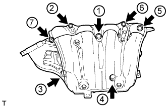
Tighten the 5 bolts and 2 nuts in the order shown in the illustration.
- Torque:
- 30 N*m { 306 kgf*cm, 22 ft.*lbf }
-
Connect the oxygen sensor connector and 2 wire harness clamps.
-
-
CONNECT UNION TO VACUUM TUBE HOSE
-
Connect the union to vacuum tube hose to the intake manifold.
-
-
CONNECT NO. 2 VENTILATION HOSE
-
Connect the No. 2 ventilation hose to the intake manifold.
-
-
INSTALL FUEL DELIVERY PIPE
-
Install 4 new injector vibration insulators to the cylinder head.
-
Install the 2 fuel delivery spacers onto the cylinder head.
-
Install the fuel delivery pipe sub-assembly with the 4 fuel injector assemblies and install the 2 bolts.
- Torque:
- 20 N*m { 204 kgf*cm, 15 ft.*lbf }
Note
-
Do not drop the fuel injector assemblies when installing the fuel delivery pipe sub-assembly.
-
Check that the fuel injector assemblies rotate smoothly after installing the fuel delivery pipe sub-assembly.
-
Connect the 4 fuel injector connectors.
-
Install the 2 wire harness clamps.
-
-
INSTALL THROTTLE WITH MOTOR BODY ASSEMBLY
-
Text in Illustration *a Groove *b Protrusion Install a new gasket to the intake manifold.
Tech Tips
Align the protrusion of the gasket with the groove on the intake manifold.
-
Temporarily install the throttle with motor body assembly and fuel tube bracket with the 4 bolts.
-
Connect the 2 water by-pass hoses.
-
Connect the purge line hose.
-
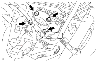
Install the fuel tube bracket and the throttle with motor body assembly with the 4 bolts.
- Torque:
- 30 N*m { 306 kgf*cm, 22 ft.*lbf }
-
Connect the throttle with motor body assembly connector to the throttle with motor body assembly.
-
Connect the wire harness clamp to the fuel tube bracket.
-
Install the fuel tube to the fuel tube bracket.
-
-
INSTALL IDLER PULLEY BRACKET
-
Install the idler pulley bracket with the 2 bolts.
- Torque:
- 50 N*m { 510 kgf*cm, 37 ft.*lbf }
-
-
INSTALL ENGINE HANGERS
-
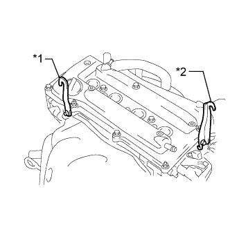
Text in Illustration *1 No. 1 Engine Hanger *2 No. 2 Engine Hanger Install the 2 engine hangers with the 2 bolts.
- Torque:
- 38 N*m { 387 kgf*cm, 28 ft.*lbf }
Part Name Part No. No. 1 engine hanger 12281-28010 No. 2 engine hanger 12282-28010 Bolt 91552-B1020
-