ENGINE UNIT INSPECTION

-
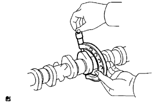
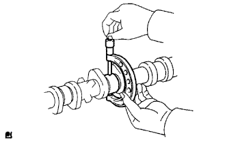
INSPECT BALANCE SHAFT THRUST CLEARANCE
-
Install the balance shafts Click here.
-
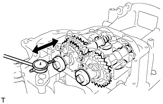
Using a dial indicator, measure the thrust clearance while moving the balance shaft back and forth.
Standard thrust clearance 0.05 to 0.09 mm (0.00197 to 0.00354 in.) Maximum thrust clearance 0.09 mm (0.00354 in.) If the thrust clearance is greater than the maximum, replace the balance shaft housing and bearings. If necessary, replace the balance shaft.
-
-
INSPECT BALANCE SHAFT OIL CLEARANCE
-
Clean each bearing and journal.
-
Check each bearing and journal for pitting and scratches.
If a bearing or journal is damaged, replace the bearings. If necessary, replace the balance shaft.
-
Place the No. 1 and No. 2 balance shafts onto the stiffening crankcase assembly.
-
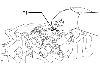
Text in Illustration *1 Plastigage Lay a strip of Plastigage across each journal.
-
Install the balance shaft housing Click here.
Note
Do not turn the balance shafts.
-
Remove the balance shaft housing Click here.
-
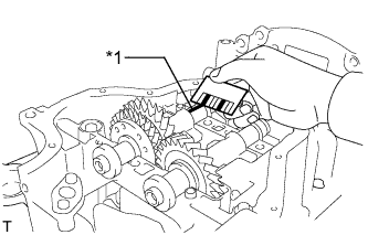
Text in Illustration *1 Plastigage Measure the Plastigage at its widest point.
Standard oil clearance 0.022 to 0.049 mm (0.000866 to 0.00193 in.) Maximum oil clearance 0.049 mm (0.00193 in.) Note
Remove the Plastigage completely after the measurement.
If the oil clearance is greater than the maximum, replace the bearing. If necessary, replace the balance shaft.
-
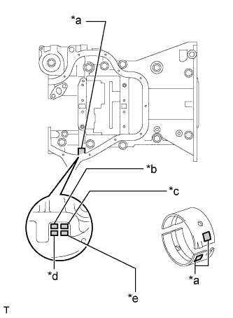
Text in Illustration *a Number Mark *b Front No. 1 Journal Bore *c Rear No. 1 Journal Bore *d Front No. 2 Journal Bore *e Rear No. 2 Journal Bore If replacing a bearing, select a new one with the same number.
Standard Balance Shaft Housing Journal Bore Diameter Item Specified Condition Mark 1 26.000 to 26.006 mm (1.0236 to 1.0239 in.) Mark 2 26.007 to 26.012 mm (1.0239 to 1.0241 in.) Mark 3 26.013 to 26.018 mm (1.0241 to 1.0243 in.) Standard Bearing Center Wall Thickness Item Specified Condition Mark 1 1.486 to 1.489 mm (0.05850 to 0.05862 in.) Mark 2 1.490 to 1.492 mm (0.05866 to 0.05874 in.) Mark 3 1.493 to 1.495 mm (0.0588 to 0.0589 in.) Standard balance shaft journal diameter 22.985 to 23.000 mm (0.9049 to 0.9055 in.) -
Inspect the balance shaft housing bolts.
-
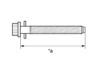
Text in Illustration *a Measurement Length Using a vernier caliper, measure the length of the balance shaft housing bolts from the seat to the end.
Standard bolt length 58.3 to 59.7 mm (2.295 to 2.350 in.) Maximum bolt length 60.3 mm (2.374 in.) If the balance shaft housing bolt length is greater than the maximum, replace the balance shaft housing bolt.
-
-
-
INSPECT CHAIN SUB-ASSEMBLY
-
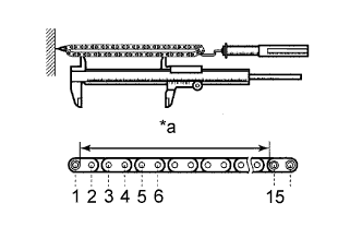
Text in Illustration *a Measurement Area Pull the chain with a force of 140 N (14 kgf, 31.5 lbf) as shown in the illustration.
-
Using a vernier caliper, measure the length of 15 links.
Maximum chain elongation 114.5 mm (4.508 in.) Note
Perform the measurement at 3 random places. Use the average of the measurements.
If the elongation is greater than the maximum, replace the chain sub-assembly.
-
-
INSPECT NO. 2 CHAIN SUB-ASSEMBLY
-
Text in Illustration *a Measurement Area Pull the chain with a force of 140 N (14 kgf, 31.5 lbf) as shown in the illustration.
-
Using a vernier caliper, measure the length of 15 links.
Maximum chain elongation 102.2 mm (4.024 in.) Note
Perform the measurement at 3 random places. Use the average of the measurements.
If the elongation is greater than the maximum, replace the No. 2 chain sub-assembly.
-
-
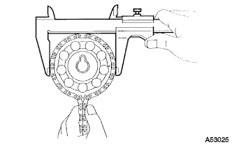
INSPECT OIL PUMP DRIVE GEAR
-
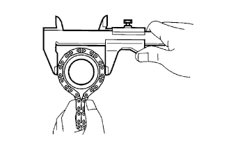
Place the chain around the oil pump drive gear.
-
Using a vernier caliper, measure the oil pump drive gear diameter of the oil pump drive gear and No. 2 chain sub-assembly.
Minimum gear diameter (with chain) 48.2 mm (1.898 in.) Note
The vernier caliper must be in contact with the chain rollers when measuring.
If the diameter is less than the minimum, replace the oil pump drive gear and No. 2 chain sub-assembly.
-
-
INSPECT OIL PUMP DRIVE SHAFT GEAR
-
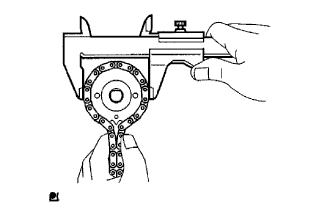
Place the chain around the oil pump drive shaft gear.
-
Using a vernier caliper, measure the sprocket diameter of the oil pump drive shaft gear and No. 2 chain sub-assembly.
Minimum gear diameter (with chain) 48.2 mm (1.898 in.) Note
The vernier caliper must be in contact with the chain rollers when measuring.
If the diameter is less than the minimum, replace the oil pump drive shaft gear and No. 2 chain sub-assembly.
-
-
INSPECT CAMSHAFT TIMING GEAR ASSEMBLY
-
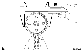
Place the chain sub-assembly around the camshaft timing gear assembly.
-
Using a vernier caliper, measure the sprocket diameter of the camshaft timing gear assembly and chain sub-assembly.
Minimum gear diameter (with chain) 97.3 mm (3.831 in.) Note
The vernier caliper must be in contact with the chain rollers when measuring.
If the diameter is less than the minimum, replace the camshaft timing gear assembly and chain sub-assembly.
-
-
INSPECT CAMSHAFT TIMING SPROCKET
-
Place the chain sub-assembly around the camshaft timing sprocket.
-
Using a vernier caliper, measure the sprocket diameter of the camshaft timing sprocket and chain sub-assembly.
Minimum gear diameter (with chain) 97.3 mm (3.831 in.) Note
The vernier caliper must be in contact with the chain rollers when measuring.
If the diameter is less than the minimum, replace the camshaft timing sprocket and chain sub-assembly.
-
-
INSPECT CRANKSHAFT TIMING SPROCKET
-
Place the chain sub-assembly around the crankshaft timing sprocket.
-
Using a vernier caliper, measure the timing gear diameter of the camshaft timing sprocket and chain sub-assembly.
Minimum gear diameter (with chain) 51.6 mm (2.031 in.) Note
The vernier caliper must be in contact with the chain rollers when measuring.
If the gear diameter is less than the minimum, replace the camshaft timing sprocket and chain sub-assembly.
-
-
INSPECT CHAIN TENSIONER SLIPPER
-
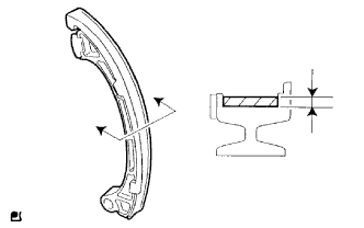
Using a vernier caliper, measure the tensioner slipper wear.
Maximum wear 1.0 mm (0.0394 in.) If the wear is greater than the maximum, replace the chain tensioner slipper.
-
-
INSPECT NO. 1 CHAIN VIBRATION DAMPER
-
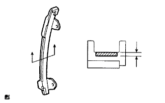
Using a vernier caliper, measure the No. 1 chain vibration damper wear.
Maximum wear 1.0 mm (0.0394 in.) If the wear is greater than the maximum, replace the No. 1 chain vibration damper.
-
-
INSPECT CHAIN TENSIONER PLATE
-
Using a vernier caliper, measure the chain tensioner plate wear.
Maximum wear 0.5 mm (0.0197 in.) If the wear is greater than the maximum, replace the chain tensioner plate.
-
-
INSPECT NO. 1 CHAIN TENSIONER ASSEMBLY
-
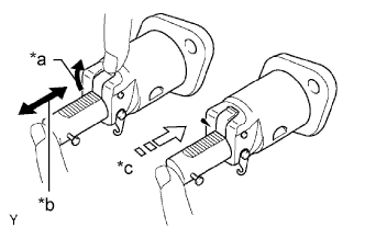
Text in Illustration *a Raise *b Move *c Lock Check that the plunger moves smoothly when the ratchet pawl is raised with your finger.
-
Release the ratchet pawl, then check that the plunger is locked in place by the ratchet pawl and does not move when pushed with your finger.
If operation is not as specified, replace the No. 1 chain tensioner assembly.
-
-
INSPECT CAMSHAFT
-
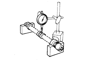
Inspect the camshaft for runout.
-
Place the camshaft on V-blocks.
-
Using a dial indicator, measure the circle runout at the center journal.
Maximum circle runout 0.03 mm (0.00118 in.) If the circle runout is greater than the maximum, replace the camshaft.
-
-
Inspect the cam lobes.
-
Using a micrometer, measure the cam lobe heights.
Standard cam lobe height 46.709 to 46.809 mm (1.8389 to 1.8429 in.) Minimum cam lobe height 46.599 mm (1.8346 in.) If any of the cam lobe heights are less than the minimum, replace the camshaft.
-
-
Inspect the camshaft journals.
-
Using a micrometer, measure the camshaft journal diameter.
Standard Journal Diameter Journal Position Specified Condition No. 1 35.971 to 35.985 mm (1.4162 to 1.4167 in.) Others 22.959 to 22.975 mm (0.9039 to 0.9045 in.) If the camshaft journal diameter is not as specified, check the oil clearance.
-
-
-
INSPECT NO. 2 CAMSHAFT
-
Inspect the No. 2 camshaft for runout.
-
Place the camshaft on V-blocks.
-
Using a dial indicator, measure the circle runout at the center journal.
Maximum circle runout 0.03 mm (0.00118 in.) If the circle runout is greater than the maximum, replace the No. 2 camshaft.
-
-
Inspect the cam lobes.
-
Using a micrometer, measure the cam lobe heights.
Standard cam lobe height 46.063 to 46.163 mm (1.8135 to 1.8174 in.) Minimum cam lobe height 45.953 mm (1.8092 in.) If any of the cam lobe heights are less than the minimum, replace the No. 2 camshaft.
-
-
Inspect the camshaft No. 2 camshaft.
-
Using a micrometer, measure the No. 2 camshaft journal diameter.
Standard Journal Diameter Journal Position Specified Condition No. 1 35.971 to 35.985 mm (1.4162 to 1.4167 in.) Others 22.959 to 22.975 mm (0.9039 to 0.9045 in.) If the No. 2 camshaft journal diameter is not as specified, check the oil clearance.
-
-
-
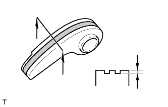
INSPECT EXHAUST MANIFOLD CONVERTER SUB-ASSEMBLY
-
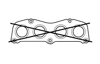
Using a precision straightedge and feeler gauge, measure the surface contacting the exhaust manifold converter sub-assembly for warpage.
Maximum warpage 0.70 mm (0.0276 in.) If the warpage is greater than the maximum, replace the exhaust manifold converter sub-assembly.
-