CAMSHAFT REMOVAL

-
REMOVE FRONT WHEEL RH
-
REMOVE FRONT WHEEL OPENING EXTENSION PAD RH
-
REMOVE ENGINE UNDER COVER RH
-
REMOVE FRONT FENDER APRON SEAL RH
-
REMOVE WINDSHIELD WIPER MOTOR AND LINK ASSEMBLY
-
REMOVE FRONT OUTER COWL TOP PANEL SUB-ASSEMBLY
-
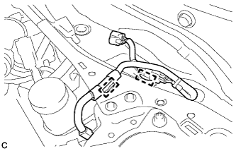
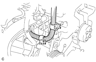
Disengage the 2 clamps and separate the wire harness from the front outer cowl top panel sub-assembly.
-
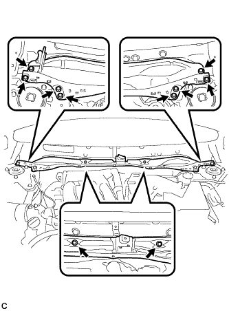
Remove the 10 bolts and front outer cowl top panel sub-assembly.
-
-
REMOVE NO. 1 ENGINE COVER SUB-ASSEMBLY
-
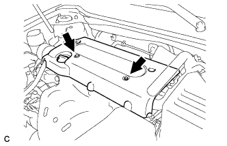
Remove the 2 nuts and No. 1 engine cover sub-assembly.
-
-
REMOVE COOL AIR INTAKE DUCT SEAL
-
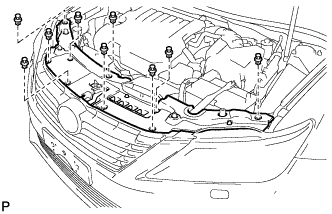
Remove the 9 clips and cool air intake duct seal.
-
-
REMOVE INLET AIR CLEANER ASSEMBLY
-
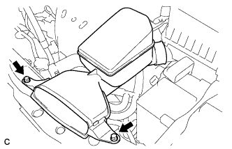
Remove the 2 bolts and inlet air cleaner assembly.
-
-
REMOVE AIR CLEANER CAP SUB-ASSEMBLY
-
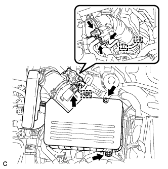
Disconnect the vacuum switching valve connector.
-
Disconnect the 2 vacuum switching valve vacuum hoses.
-
Disconnect the purge line hose from the 2 clamps.
-
Disconnect the mass air flow meter connector.
-
Disconnect the wire harness clamp.
-
Loosen the 2 bolts and separate the air cleaner cap sub-assembly.
-
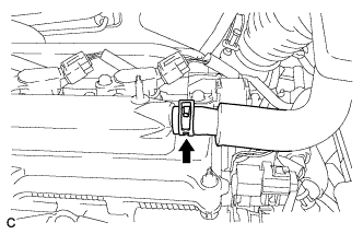
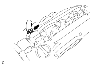
Disconnect the ventilation hose from the cylinder head cover sub-assembly.
-
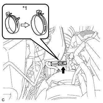
Text in Illustration *1 Air Cleaner Hose Clamp Lock the air cleaner hose clamp as shown in the illustration, and disconnect the air cleaner cap sub-assembly from the throttle with motor body assembly.
-
Remove the air cleaner filter element from the air cleaner case sub-assembly.
-
-
REMOVE AIR CLEANER CASE SUB-ASSEMBLY
-
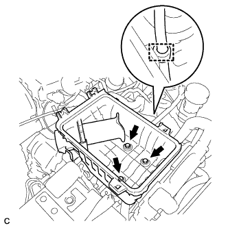
Disconnect the wire harness clamp.
-
Remove the 3 bolts and air cleaner case sub-assembly.
-
-
REMOVE IGNITION COIL ASSEMBLY
-
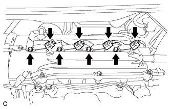
Disconnect the 4 ignition coil assembly connectors.
-
Remove the 4 bolts and 4 ignition coil assemblies.
-
-
REMOVE CYLINDER HEAD COVER SUB-ASSEMBLY
-
Disconnect the No. 2 ventilation hose from the cylinder head cover sub-assembly.
-
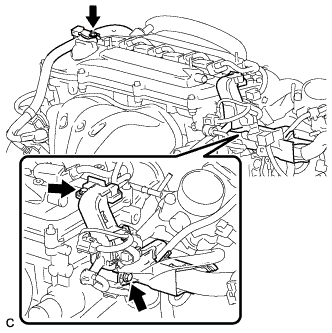
Remove the 3 bolts and separate the engine wire.
-
Disconnect the 2 wire harness clamps.
-
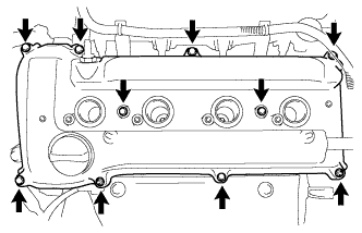
Remove the 8 bolts, 2 nuts and cylinder head cover sub-assembly.
-
Remove the cylinder head cover gasket.
-
-
SET NO. 1 CYLINDER TO TDC/COMPRESSION
-
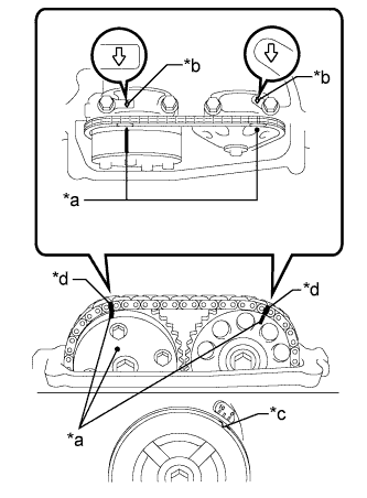
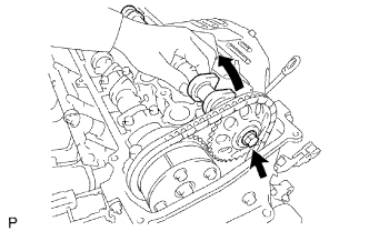
Text in Illustration *a Timing Mark *b Front Mark *c Groove *d Paint Mark Turn the crankshaft pulley until its groove and the timing mark "0" of the timing chain cover sub-assembly are aligned.
-
Check that each timing mark of the camshaft timing gear assembly and camshaft timing sprocket is aligned with each front mark located on the No. 1 and No. 2 bearing caps as shown in the illustration.
If not, turn the crankshaft by 1 revolution (360°) to align the timing marks as above.
-
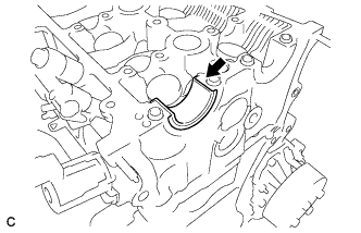
Place paint marks on the chain sub-assembly in alignment with the timing marks on the camshaft timing gear assembly and camshaft timing sprocket.
-
-
REMOVE NO. 1 CHAIN TENSIONER ASSEMBLY
-
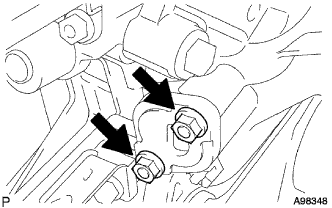
Remove the 2 nuts, No. 1 chain tensioner assembly and chain tensioner gasket.
Note
Do not turn the crankshaft without the No. 1 chain tensioner assembly.
-
-
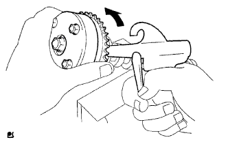
LOOSEN CAMSHAFT TIMING SPROCKET
-
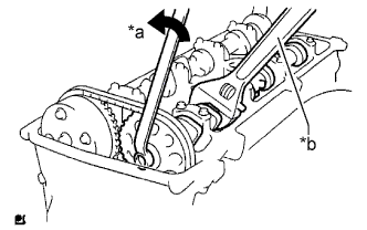
Text in Illustration *a Loosen *b Hold While holding the No. 2 camshaft with a wrench, loosen the bolt.
-
-
REMOVE NO. 2 CAMSHAFT
-
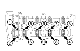
Using several steps, uniformly remove the 10 bolts in the order shown in the illustration.
-
Remove the 5 camshaft bearing caps.
-
While holding the No. 2 camshaft by hand, remove the bolt.
-
Remove the camshaft timing sprocket and No. 2 camshaft.
-
-
REMOVE CAMSHAFT
-
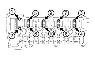
Using several steps, uniformly remove the 10 bolts in the order shown in the illustration.
-
Remove the 5 camshaft bearing caps.
-
Remove the camshaft and camshaft timing gear assembly.
-
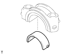
Remove the No. 1 camshaft bearing from the No. 1 camshaft bearing cap.
-
Remove the No. 2 camshaft bearing from the cylinder head sub-assembly.
-
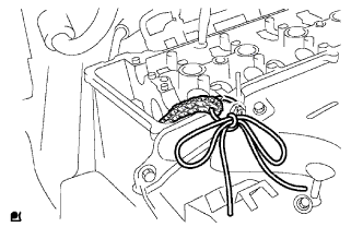
Support the chain sub-assembly with a string to prevent it from slipping off the crankshaft timing sprocket as shown in the illustration.
Note
Be careful not to drop anything inside the timing chain cover sub-assembly.
-
-
REMOVE CAMSHAFT TIMING GEAR ASSEMBLY
-
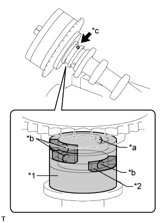
Text in Illustration *1 Vinyl Tape *2 Rubber Piece *a Open *b Close *c Advance Side Path Clamp the camshaft in a vise, and make sure that the camshaft timing gear assembly does not rotate.
-
Cover all the oil paths with vinyl tape except the advance side path shown in the illustration.
-
Apply air pressure of 150 kPa (1.5 kgf/cm2, 22 psi) to the open oil path, then turn the camshaft timing gear assembly to the advance direction (counterclockwise) by hand.
CAUTION:
Cover the paths with a piece of cloth to avoid oil splashes.
Tech Tips
Depending on the air pressure, the camshaft timing gear assembly may turn to the advance side without applying force by hand. Also, if the pressure is difficult to apply because of air leakage from a path, the lock pin may be difficult to release.
-
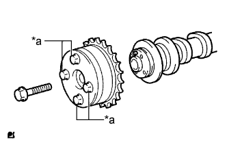
Text in Illustration *a Do Not Remove Remove the bolt and camshaft timing gear assembly.
Note
-
Be sure not to remove the other 4 bolts.
-
When reusing the camshaft timing gear, release the lock pin first, then install the gear.
-
-