ENGINE UNIT REMOVAL

-
REMOVE ENGINE HANGERS
-
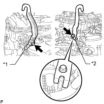
Text in Illustration *1 No. 1 Engine Hanger *2 No .2 Engine Hanger Remove the 2 bolts and 2 engine hangers.
-
-
REMOVE ENGINE OIL LEVEL DIPSTICK GUIDE
-
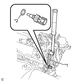
Remove the engine oil level dipstick.
-
Remove the bolt and engine oil level dipstick guide.
-
Remove the O-ring from the engine oil level dipstick guide.
-
-
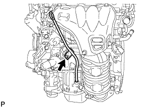
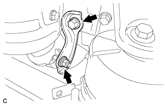
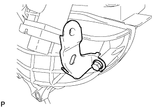
REMOVE MANIFOLD STAY
-
Remove the bolt, nut and manifold stay.
-
-
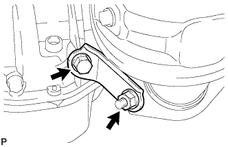
REMOVE NO. 2 MANIFOLD STAY
-
Remove the bolt, nut and No. 2 manifold stay.
-
-
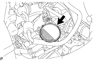
REMOVE NO. 1 EXHAUST MANIFOLD HEAT INSULATOR
-
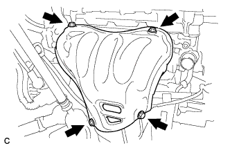
Remove the 4 bolts and No. 1 exhaust manifold heat insulator.
-
-
REMOVE EXHAUST MANIFOLD CONVERTER SUB-ASSEMBLY
-
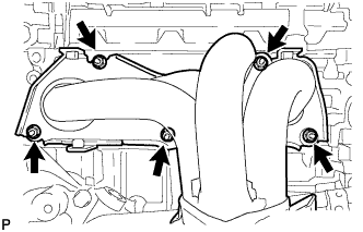
Remove the 5 nuts and exhaust manifold converter sub-assembly.
-
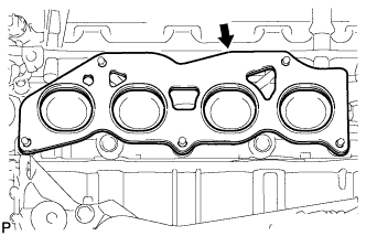
Remove the exhaust manifold to head gasket.
-
-
REMOVE NO. 1 COMPRESSOR MOUNTING BRACKET
-
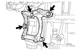
Remove the 4 bolts and bracket.
-
-
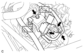
REMOVE THROTTLE WITH MOTOR BODY ASSEMBLY
-
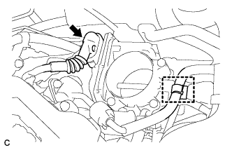
Disconnect the fuel tube from the clamp.
-
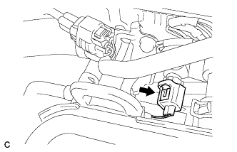
Disconnect the throttle body connector.
-
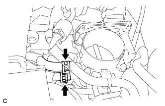
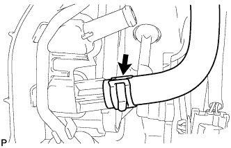
Disconnect the water by-pass hose from the throttle with motor body assembly.
-
Disconnect the No. 2 water by-pass hose from the throttle with motor body assembly.
-
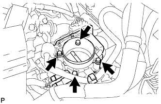
Remove the 4 bolts and the throttle body with fuel tube bracket.
-
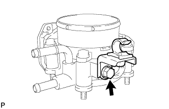
Remove the bolt and fuel tube bracket.
-
Remove the gasket from the intake manifold.
-
-
REMOVE WATER BY-PASS HOSE
-
Remove the No. 1 and No. 2 water by-pass hoses.
-
-
REMOVE VACUUM SWITCHING VALVE ASSEMBLY (for ACIS)
-
Disconnect the union to connector tube hose and wire harness clamp.
-
Disconnect the 2 vacuum hoses and connector.
-
Remove the bolt and vacuum switching valve assembly.
-
-
DISCONNECT NO. 2 VENTILATION HOSE
-
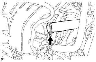
Disconnect the No. 2 ventilation hose from the intake manifold.
-
-
REMOVE UNION TO CONNECTOR TUBE HOSE (for LHD)
-
Disconnect the union to connector tube hose from the intake manifold.
-
-
REMOVE UNION TO CHECK VALVE HOSE (for RHD)
-
Disconnect the union to connector tube hose from the intake manifold.
-
-
REMOVE FUEL DELIVERY PIPE SUB-ASSEMBLY
-
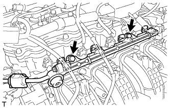
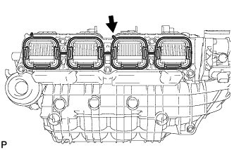
Remove the 2 bolts, and then remove the fuel delivery pipe together with the 4 fuel injectors.
Note
Be careful not to drop the fuel injectors when removing the fuel delivery pipe.
-
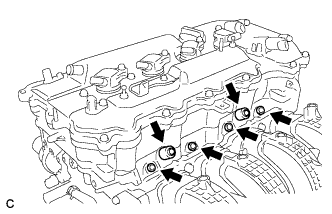
Remove the 2 fuel delivery spacers from the cylinder head.
-
Remove the 4 injector vibration insulators from the cylinder head.
-
-
REMOVE INTAKE MANIFOLD
-
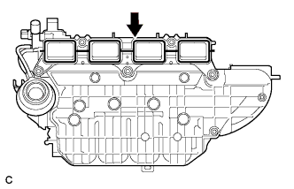
Remove the 2 bolts and 2 wire harness clamp brackets.
-
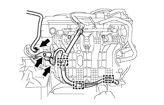
Disconnect the fuel vapor feed hose.
-
Disconnect the 3 wire harness clamps and connector.
-
Remove the bolt and wire harness clamp bracket.
-
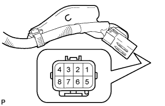
Apply battery voltage to the terminals of the connector to close the tumble control valves (w/ TCV).
Standard Tester Connection Specified Condition Positive (+) battery voltage applied to terminal 8 (M-), and negative (-) battery voltage applied to terminal 4 (M+) Open → Closed Note
-
If this procedure is not performed, the tumble control valves may be damaged when the intake manifold is removed.
-
Apply battery voltage for 1 to 3 seconds.
-
If battery voltage is applied for more than 3 seconds, the actuator may be damaged.
-
Do not allow the lead wires to contact the other terminals.
-
-
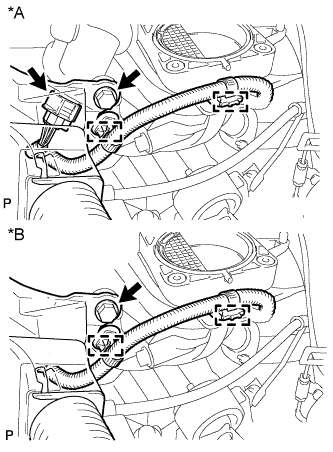
Remove the bolt and separate the wire harness.
-
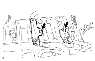
Disconnect the 2 wire harness clamps and intake air control valve actuator connector (w/ TCV).
-
Disconnect the 2 wire harness clamps (w/o TCV).
Text in Illustration *A w/ TCV *B w/o TCV -
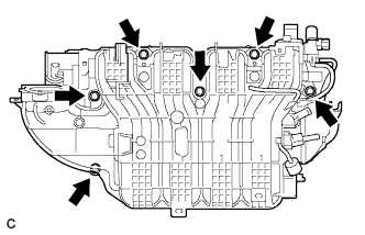
Remove the 6 bolts and intake manifold (w/ TCV).
Note
The tumble control valves may be damaged if they are not closed before removing the intake manifold.
Tech Tips
Connect the battery to the terminals of the actuator to operate the motor and close the valves Click here.
-
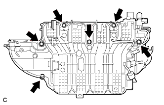
Remove the 6 bolts and intake manifold (w/o TCV).
-
Remove the intake manifold gasket from the intake manifold (w/ TCV).
-
Remove the intake manifold gasket from the intake manifold (w/o TCV).
-
Disconnect the 2 vacuum hoses from the intake manifold and remove the No. 1 check valve.
-
Remove the bolt and wire harness clamp bracket.
-
-
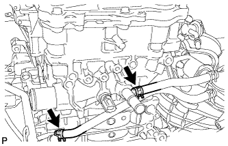
REMOVE SENSOR WIRE
-
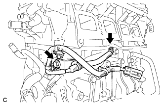
Disconnect the knock control sensor connector.
-
Remove the bolt and knock control sensor wire.
-
-
REMOVE KNOCK CONTROL SENSOR
-
Disconnect the sensor connector.
-
Remove the bolt and knock control sensor.
-
-
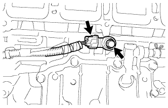
REMOVE ENGINE OIL PRESSURE SWITCH ASSEMBLY
-
Disconnect the connector.
-
Using a 24 mm deep socket wrench, remove the oil pressure switch.
-
-
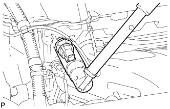
REMOVE ENGINE COOLANT TEMPERATURE SENSOR
-
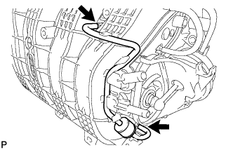
Disconnect the engine coolant temperature sensor connector.
-
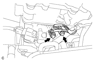
Remove the 2 bolts and disconnect the wire harness.
-
Text in Illustration *1 Ball Joint Lock Nut Wrench *2 Gasket Using a 19 mm ball joint lock nut wrench, remove the engine coolant temperature sensor.
-
Remove the gasket from the engine coolant temperature sensor.
-
-
REMOVE IGNITION COIL ASSEMBLY
-
Disconnect the 4 ignition coil assembly connectors.
-
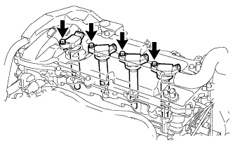
Remove the 4 bolts and 4 ignition coil assemblies.
-