CYLINDER HEAD GASKET INSTALLATION

-
INSTALL CYLINDER HEAD GASKET
-
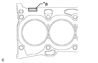
Text in Illustration *a Lot No. Place a new cylinder head gasket on the cylinder block surface with the lot No. stamp facing upward.
Note
-
Remove any oil from the contact surfaces.
-
Be careful of the installation direction.
-
-
-
INSTALL CYLINDER HEAD SUB-ASSEMBLY
Tech Tips
The cylinder head set bolts are tightened in 2 progressive steps.
-
Place the cylinder head sub-assembly on the cylinder head gasket.
Note
Place the cylinder head sub-assembly gently in order to avoid damaging the cylinder head gasket.
-
Apply a light coat of engine oil to the threads and under the heads of the 10 cylinder head set bolts.
-
Set the 10 plate washers and 10 cylinder head set bolts.
-
Step 1:
-
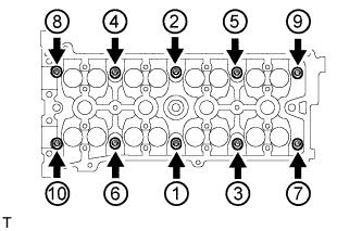
Using a 10 mm bi-hexagon wrench, uniformly tighten the 10 cylinder head set bolts in several steps, in the order shown in the illustration.
- Torque:
- 70 N*m { 714 kgf*cm, 51 ft.*lbf }
-
-
Step 2:
-
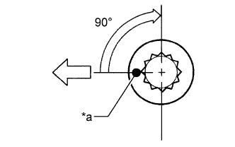
Text in Illustration *a Paint Mark 
Engine Front Mark the front of the cylinder head set bolts with paint.
-
Tighten the cylinder head set bolts 90° in the sequence shown in step 1.
-
-
Check that the paint mark is now at a 90° angle to the front.
-
-
INSTALL EXHAUST MANIFOLD CONVERTER SUB-ASSEMBLY
-
Set a new gasket to the cylinder head sub-assembly.
-
Temporarily install the exhaust manifold converter sub-assembly with the 5 nuts.
-
Temporarily install the No. 2 manifold stay and manifold stay with the 2 bolts and 2 nuts.
-
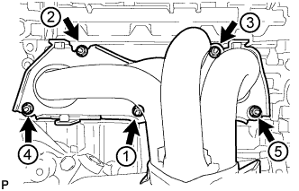
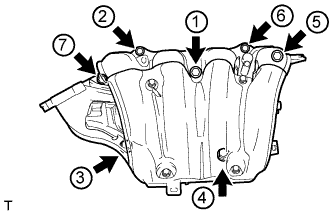
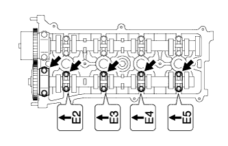
Using a 12 mm deep socket wrench, install the exhaust manifold converter sub-assembly and 5 nuts in the order shown in the illustration.
- Torque:
- 37 N*m { 377 kgf*cm, 27 ft.*lbf }
-
Connect the air fuel ratio sensor connector.
-
-
INSTALL NO. 2 MANIFOLD STAY
-
Install the No. 2 manifold stay with the bolt and nut.
- Torque:
- 44 N*m { 449 kgf*cm, 32 ft.*lbf }
-
-
INSTALL MANIFOLD STAY
-
Install the manifold stay with the bolt and nut.
- Torque:
- 44 N*m { 449 kgf*cm, 32 ft.*lbf }
-
-
INSTALL NO. 1 EXHAUST MANIFOLD HEAT INSULATOR
-
Install the No. 1 exhaust manifold heat insulator with the 4 bolts.
- Torque:
- 12 N*m { 122 kgf*cm, 9 ft.*lbf }
-
-
INSTALL NO. 1 INTAKE MANIFOLD INSULATOR
-
Install the No. 1 intake manifold insulator to the cylinder block.
-
-
INSTALL INTAKE MANIFOLD
-
Install the vacuum hose clamp with the bolt.
- Torque:
- 5.4 N*m { 55 kgf*cm, 48 in.*lbf }
-
Install a new No. 1 intake manifold to head gasket to the intake manifold.
-
Set the intake manifold on the engine assembly.
-
Using an E7 "TORX" wrench, install the 2 stud bolts.
- Torque:
- 9.5 N*m { 97 kgf*cm, 84 in.*lbf }
-
Temporarily install the intake manifold with the 5 bolts and 2 nuts.
-
Tighten the 5 bolts and 2 nuts in the order shown in the illustration.
- Torque:
- 30 N*m { 306 kgf*cm, 22 ft.*lbf }
-
Connect the oxygen sensor connector and 2 wire harness clamps.
-
-
INSTALL THROTTLE WITH MOTOR BODY ASSEMBLY
-
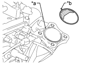
Text in Illustration *a Groove *b Protrusion Install a new gasket to the intake manifold.
Tech Tips
Align the protrusion of the gasket with the groove on the intake manifold.
-
Temporarily install the throttle with motor body assembly and fuel tube bracket with the 4 bolts.
-
Connect the 2 water by-pass hoses.
-
Connect the purge line hose.
-
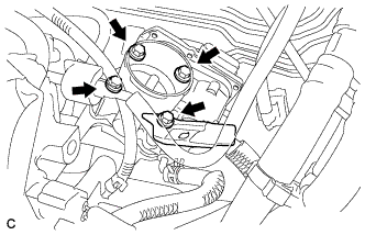
Install the fuel tube bracket and the throttle with motor body assembly with the 4 bolts.
- Torque:
- 30 N*m { 306 kgf*cm, 22 ft.*lbf }
-
Connect the throttle with motor body assembly connector to the throttle with motor body assembly.
-
Connect the wire harness clamp to the fuel tube bracket.
-
Install the fuel tube to the fuel tube bracket.
-
-
CONNECT ENGINE WIRE
-
Connect the 4 connectors.
-
Connect the earth wire with the bolt.
- Torque:
- 8.0 N*m { 82 kgf*cm, 72 in.*lbf }
-
-
INSTALL CAMSHAFT
-
Apply a light coat of engine oil to the camshaft journals, camshaft housings and bearing caps.
-
Install the No. 1 camshaft bearing and No. 2 camshaft bearing.
-
Examine the front marks and numbers, and check that the order is as shown in the illustration. Then temporarily install the camshaft and 5 camshaft bearing caps with the 10 bolts.
-
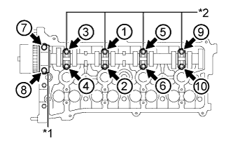
Text in Illustration *1 No. 1 Camshaft Bearing Cap *2 No. 3 Camshaft Bearing Cap Using several steps, uniformly tighten the 10 bolts in the order shown in the illustration.
- Torque:
- No. 1 camshaft bearing cap
- 30 N*m { 301 kgf*cm, 22 ft.*lbf }
- No. 3 camshaft bearing cap
- 9.0 N*m { 92 kgf*cm, 80 in.*lbf }
-
-
INSTALL NO. 2 CAMSHAFT
-
Apply a light coat of engine oil to the camshaft journals, camshaft housings and bearing caps.
-
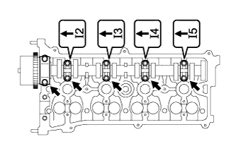
Examine the front marks and numbers, and check that the order is as shown in the illustration. Then temporarily install the No. 2 camshaft and 5 camshaft bearing caps with the 10 bolts.
-
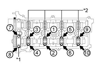
Text in Illustration *1 No. 2 Camshaft Bearing Cap *2 No. 3 Camshaft Bearing Cap Using several steps, uniformly tighten the 10 bolts in the order shown in the illustration.
- Torque:
- No. 2 camshaft bearing cap
- 30 N*m { 301 kgf*cm, 22 ft.*lbf }
- No. 3 camshaft bearing cap
- 9.0 N*m { 92 kgf*cm, 80 in.*lbf }
-
-
INSTALL NO. 1 CHAIN VIBRATION DAMPER
-
Install the No. 1 chain vibration damper with the 2 bolts.
- Torque:
- 9.0 N*m { 92 kgf*cm, 80 in.*lbf }
-
-
INSTALL CHAIN SUB-ASSEMBLY
-
Set the No. 1 cylinder to TDC/compression.
-
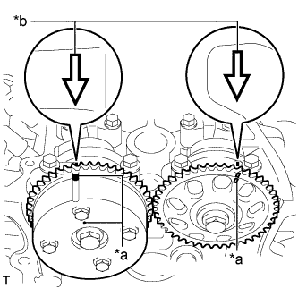
Text in Illustration *a Timing Mark *b Front Mark Using the hexagonal portion of the camshafts, rotate the camshafts with a wrench, align the timing marks on the camshaft timing gear assembly and camshaft timing sprocket with the front marks located on the No. 1 camshaft bearing cap and No. 2 camshaft bearing cap as shown in the illustration.
-
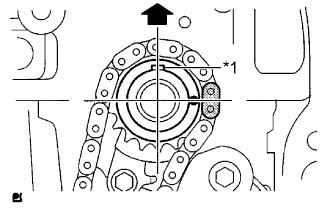
Text in Illustration *1 Crankshaft Key 
Up Check that the crankshaft is positioned with the crankshaft key facing up as shown in the illustration.
-
-
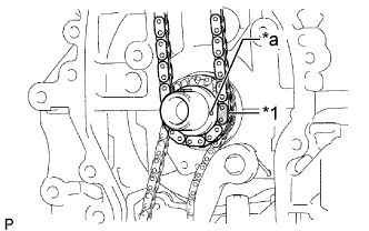
Text in Illustration *1 Mark Link *a Timing Mark Install the chain onto the crankshaft timing sprocket with the gold or pink mark link aligned with the timing mark on the crankshaft.
-
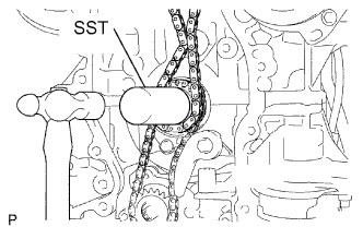
Using SST and a hammer, tap in the crankshaft timing sprocket.
- SST
- 09309-37010
-
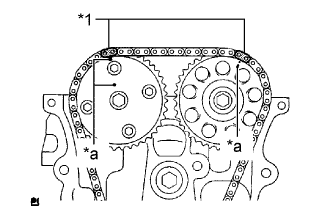
Text in Illustration *1 Mark Link *a Timing Mark Align the gold or yellow links with the timing marks located on the camshaft timing gear assembly and camshaft timing sprocket, then install the chain sub-assembly.
-
-
INSTALL CHAIN TENSIONER SLIPPER
-
Install the chain tensioner slipper with the bolt.
- Torque:
- 19 N*m { 194 kgf*cm, 14 ft.*lbf }
-
-
INSTALL TIMING CHAIN GUIDE
-
Install the timing chain guide with the bolt.
- Torque:
- 9.0 N*m { 92 kgf*cm, 80 in.*lbf }
-
-
INSTALL NO. 1 CRANKSHAFT POSITION SENSOR PLATE
-
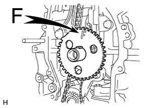
Install the No. 1 crankshaft position sensor plate with the "F" mark facing forward.
-
-
INSTALL TIMING CHAIN COVER SUB-ASSEMBLY