CAMSHAFT INSTALLATION

-
INSTALL CAMSHAFT TIMING GEAR ASSEMBLY
-
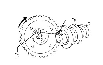
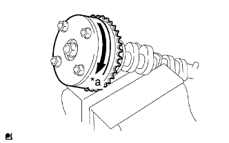
Text in Illustration *a Straight Pin *b Key Groove Put the camshaft timing gear assembly and camshaft together with the straight pin and key groove misaligned as shown in the illustration.
-
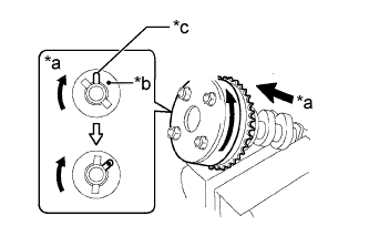
Text in Illustration *a View A *b Straight Pin *c Key Groove Turn the camshaft timing gear assembly as shown in the illustration while pushing it gently against the camshaft. Push further at the position where the pin fits into the groove.
Note
Be sure not to turn the camshaft timing gear assembly to the retard direction (clockwise).
-
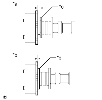
Text in Illustration *a INCORRECT *b CORRECT *c Flange Check that there is no clearance between the camshaft timing gear assembly and camshaft flange.
-
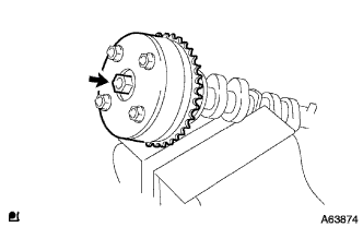
Tighten the bolt with the camshaft timing gear assembly secured in place.
- Torque:
- 54 N*m { 551 kgf*cm, 40 ft.*lbf }
-
Text in Illustration *a Lock Check that the camshaft timing gear assembly can move to the retard direction (clockwise) and is locked in the most retarded position.
-
-
INSTALL CAMSHAFT
-
Apply a light coat of engine oil to the camshaft journals, camshaft housings and bearing caps.
-
Install the No. 1 camshaft bearing and No. 2 camshaft bearing.
Note
Keep the installation surfaces and the back surfaces of the camshaft bearing free of engine oil.
-
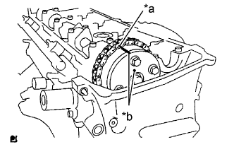
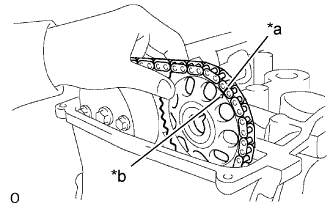
Text in Illustration *a Paint Mark *b Timing Mark Install the chain sub-assembly onto the camshaft timing gear assembly with the paint mark aligned with the timing mark on the camshaft timing gear assembly as shown in the illustration.
-
Examine the front marks and numbers, and check that the order is as shown in the illustration. Then temporarily install the 5 camshaft bearing caps with the 10 bolts.
-
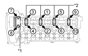
Text in Illustration *1 No. 1 Camshaft Bearing Cap *2 No. 3 Camshaft Bearing Cap Using several steps, uniformly tighten the 10 bolts in the order shown in the illustration.
- Torque:
- No. 1 camshaft bearing cap
- 30 N*m { 301 kgf*cm, 22 ft.*lbf }
- No. 3 camshaft bearing cap
- 9.0 N*m { 92 kgf*cm, 80 in.*lbf }
-
-
INSTALL NO. 2 CAMSHAFT
-
Apply a light coat of engine oil to the camshaft journals, camshaft housings and bearing caps.
-
Text in Illustration *a Paint Mark *b Timing Mark Put the camshaft timing sprocket on the cylinder head sub-assembly with the paint mark on the chain aligned with the timing mark on the camshaft timing sprocket.
-

While holding the No. 2 camshaft by hand, temporarily install the No. 2 camshaft to the camshaft timing sprocket using the bolt.
-
Examine the front marks and numbers, and check that the order is as shown in the illustration. Then temporarily install the 5 camshaft bearing caps with the 10 bolts.
-

Text in Illustration *1 No. 2 Camshaft Bearing Cap *2 No. 3 Camshaft Bearing Cap Using several steps, uniformly tighten the 10 bolts in the order shown in the illustration.
- Torque:
- No. 2 camshaft bearing cap
- 30 N*m { 301 kgf*cm, 22 ft.*lbf }
- No. 3 camshaft bearing cap
- 9.0 N*m { 92 kgf*cm, 80 in.*lbf }
-
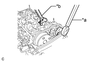
Text in Illustration *a Tighten *b Hold Using a union nut wrench, while holding the No. 2 camshaft with a wrench, tighten the bolt.
- Torque:
- 54 N*m { 551 kgf*cm, 40 ft.*lbf }
Note
-
Be careful not to damage the cylinder head sub-assembly with the wrench.
-
Use the torque value compensation formula to calculate the torque value for use when a torque wrench is combined with a tool such as a union nut wrench Click here.
-

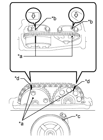
Text in Illustration *a Paint Mark *b Timing Mark *c Groove *d 7 Links Check that the paint marks on the chain sub-assembly are aligned with the timing marks on the camshaft timing gear assembly and camshaft timing sprocket. Also, check that the crankshaft pulley groove is aligned with the timing mark "0" on the timing chain cover sub-assembly.
-
-
INSTALL NO. 1 CHAIN TENSIONER ASSEMBLY
-
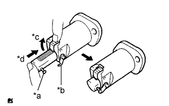
Text in Illustration *a Pin *b Hook *c Raise *d Push Release the ratchet pawl, then fully push in the plunger and set the hook to the pin so that the plunger is in the position shown in the illustration.
-
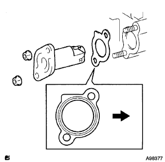
Install a new chain tensioner gasket and the No. 1 chain tensioner assembly with the 2 nuts.
Text in Illustration 
Engine Front - Torque:
- 9.0 N*m { 92 kgf*cm, 80 in.*lbf }
Note
When installing the chain tensioner, set the hook again if the hook releases the plunger.
-
-
SET NO. 1 CYLINDER TO TDC/COMPRESSION
-
Text in Illustration *a Timing Mark *b Front Mark *c Groove *d Paint Mark Turn the crankshaft pulley until its groove and the timing mark "0" of the timing chain cover sub-assembly are aligned.
-
Check that each timing mark of the camshaft timing gear assembly and camshaft timing sprocket is aligned with each front mark located on the No. 1 and No. 2 bearing caps as shown in the illustration.
If not, turn the crankshaft by 1 revolution (360°) to align the timing marks as above.
-
Place paint marks on the chain sub-assembly in alignment with the timing marks on the camshaft timing gear assembly and camshaft timing sprocket.
-
-
CHECK VALVE CLEARANCE
-
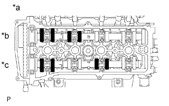
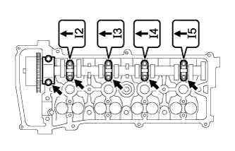
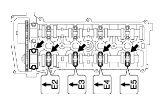
Text in Illustration *a No. 1 Cylinder TDC/Compression *b Intake Side *c Exhaust Side Check only the valves indicated.
-
Using a feeler gauge, measure the clearance between the valve lifter and camshaft.
Standard Valve Clearance (Cold) Item Specified Condition Intake 0.19 to 0.29 mm (0.00748 to 0.0114 in.) Exhaust 0.38 to 0.48 mm (0.0150 to 0.0189 in.) -
Record any out-of-specification valve clearance measurements. They will be used later to determine the required replacement valve lifters.
-
-
Turn the crankshaft 1 revolution (360°) and set the No. 4 cylinder to TDC/compression.
-
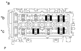
Text in Illustration *a No. 4 Cylinder TDC/Compression *b Intake Side *c Exhaust Side Check only the valves indicated.
-
Using a feeler gauge, measure the clearance between the valve lifter and camshaft.
Standard Valve Clearance (Cold) Item Specified Condition Intake 0.19 to 0.29 mm (0.00748 to 0.0114 in.) Exhaust 0.38 to 0.48 mm (0.0150 to 0.0189 in.) -
Record any out-of-specification valve clearance measurements. They will be used later to determine the required replacement valve lifters.
-
-
-
ADJUST VALVE CLEARANCE
-
Remove the camshaft Click here.
-
Remove the valve lifters.
Tech Tips
Arrange the valve lifters in the same order as removed.
-
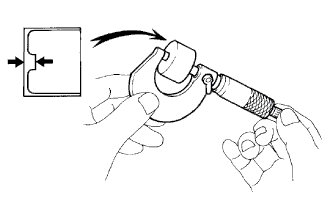
Using a micrometer, measure the thickness of the removed valve lifters.
-
Calculate the thickness of a new lifter so that the valve clearance comes within the specified range.
New Lifter Thickness Item Specification Intake A = B + (C - 0.24 mm (0.00945 in.)) Exhaust A = B + (C - 0.43 mm (0.0169 in.)) A New lifter thickness B Used lifter thickness C Measured valve clearance CALCULATION EXAMPLE (Intake):
-
Measured intake valve clearance = 0.40 mm (0.0157 in.)
(Measured - Specification = Excess clearance)
-
0.40 mm (0.0157 in.) - 0.24 mm (0.00945 in.) = 0.16 mm (0.00630 in.)
-
Measured used lifter thickness = 5.250 mm (0.207 in.)
-
New lifter thickness = 5.410 mm (0.2130 in.)
(Excess clearance + Used lifter thickness = Ideal new lifter)
-
0.16 mm (0.00630 in.) + 5.250 mm (0.207 in.) = 5.410 mm (0.2130 in.)
-
Closest new lifter = 5.420 mm (0.2134 in.)
-
Select No. 42 lifter
-
-
Select a new lifter with a thickness as close as possible to the calculated values.
Tech Tips
-
Lifters are available in 35 sizes in increments of 0.020 mm (0.000787 in.), from 5.060 to 5.740 mm (0.1992 to 0.2260 in.).
-
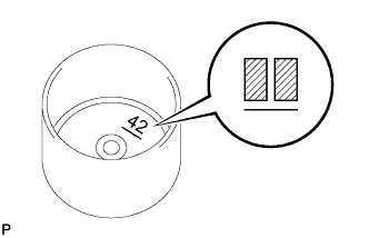
The identification number inside the valve lifters shows the value to 2 decimal places. (The illustration shows 5.420 mm (0.2134 in.))
-
-
Valve lifter selection chart (intake).
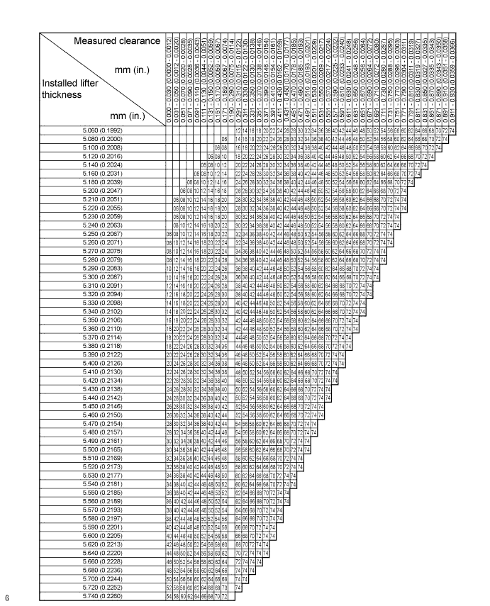
New Lifter Thickness Lifter No. Thickness mm (in.) Lifter No. Thickness mm (in.) Lifter No. Thickness mm (in.) 06 5.060 (0.1992) 30 5.300 (0.2087) 54 5.540 (0.2181) 08 5.080 (0.2000) 32 5.320 (0.2094) 56 5.560 (0.2189) 10 5.100 (0.2008) 34 5.340 (0.2102) 58 5.580 (0.2197) 12 5.120 (0.2016) 36 5.360 (0.2110) 60 5.600 (0.2205) 14 5.140 (0.2024) 38 5.380 (0.2118) 62 5.620 (0.2213) 16 5.160 (0.2031) 40 5.400 (0.2126) 64 5.640 (0.2220) 18 5.180 (0.2039) 42 5.420 (0.2134) 66 5.660 (0.2228) 20 5.200 (0.2047) 44 5.440 (0.2142) 68 5.680 (0.2236) 22 5.220 (0.2055) 46 5.460 (0.2150) 70 5.700 (0.2244) 24 5.240 (0.2063) 48 5.480 (0.2157) 72 5.720 (0.2252) 26 5.260 (0.2071) 50 5.500 (0.2165) 74 5.740 (0.2260) 28 5.280 (0.2079) 52 5.520 (0.2173) - - Standard intake valve clearance (cold) 0.19 to 0.29 mm (0.00748 to 0.0114 in.) EXAMPLE:
A 5.250 mm (0.2067 in.) lifter is installed, and the measured clearance is 0.400 mm (0.0157 in.). Replace the 5.250 mm (0.2067 in.) lifter with a new No. 42 lifter.
-
Valve lifter selection chart (exhaust).
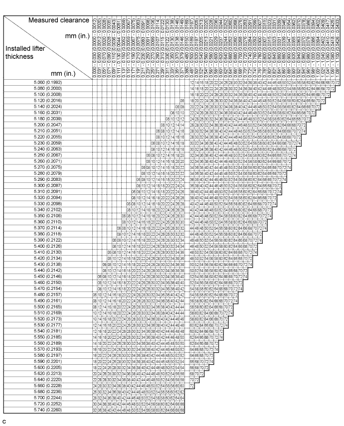
New Lifter Thickness Lifter No. Thickness mm (in.) Lifter No. Thickness mm (in.) Lifter No. Thickness mm (in.) 06 5.060 (0.1992) 30 5.300 (0.2087) 54 5.540 (0.2181) 08 5.080 (0.2000) 32 5.320 (0.2094) 56 5.560 (0.2189) 10 5.100 (0.2008) 34 5.340 (0.2102) 58 5.580 (0.2197) 12 5.120 (0.2016) 36 5.360 (0.2110) 60 5.600 (0.2205) 14 5.140 (0.2024) 38 5.380 (0.2118) 62 5.620 (0.2213) 16 5.160 (0.2031) 40 5.400 (0.2126) 64 5.640 (0.2220) 18 5.180 (0.2039) 42 5.420 (0.2134) 66 5.660 (0.2228) 20 5.200 (0.2047) 44 5.440 (0.2142) 68 5.680 (0.2236) 22 5.220 (0.2055) 46 5.460 (0.2150) 70 5.700 (0.2244) 24 5.240 (0.2063) 48 5.480 (0.2157) 72 5.720 (0.2252) 26 5.260 (0.2071) 50 5.500 (0.2165) 74 5.740 (0.2260) 28 5.280 (0.2079) 52 5.520 (0.2173) - - Standard exhaust valve clearance (cold) 0.38 to 0.48 mm (0.0150 to 0.0189 in.) EXAMPLE:
A 5.340 mm (0.2102 in.) lifter is installed, and the measured clearance is 0.510 mm (0.0201 in.). Replace the 5.340 mm (0.2102 in.) lifter with a new No. 42 lifter.
-
Install the selected valve lifter.
-
Install the camshaft Click here.
-
-
INSTALL CYLINDER HEAD COVER SUB-ASSEMBLY
-

Remove any old packing material from the contact surfaces.
-
Apply seal packing to the 2 locations shown in the illustration.
Seal packing Toyota Genuine Seal Packing Black, Three Bond 1207B or equivalent Note
-
Remove any oil from the contact surfaces.
-
Install the cylinder head cover sub-assembly within 3 minutes of applying seal packing.
-
Do not add engine oil for at least 2 hours after installing the cylinder head cover sub-assembly.
-
-
Install the cylinder head cover gasket to the cylinder head cover sub-assembly.
-
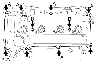
Text in Illustration *1 Nut Install the cylinder head cover sub-assembly with the 8 bolts and 2 nuts.
- Torque:
- Bolt A
- 11 N*m { 112 kgf*cm, 8 ft.*lbf }
- Bolt B
- 14 N*m { 143 kgf*cm, 10 ft.*lbf }
- Nut
- 11 N*m { 112 kgf*cm, 8 ft.*lbf }
-
Install the engine wire with the 3 bolts.
- Torque:
- 8.0 N*m { 82 kgf*cm, 72 in.*lbf }
-
Connect the 2 wire harness clamps.
-
Connect the No. 2 ventilation hose to the cylinder head cover sub-assembly.
-
-
INSTALL IGNITION COIL ASSEMBLY
-
Install the 4 ignition coil assemblies with the 4 bolts.
- Torque:
- 9.0 N*m { 92 kgf*cm, 80 in.*lbf }
-
Connect the 4 ignition coil assembly connectors.
-
-
INSPECT FOR OIL LEAK
-
INSPECT IGNITION TIMING
-
Warm up and stop the engine.
-
When using the intelligent tester:
-
Connect the intelligent tester to the DLC3.
Note
When checking the ignition timing, the transmission should be in neutral.
-
Start the engine and idle it.
-
Turn the intelligent tester main switch on.
-
Enter the following menus: Powertrain / Engine / Data List / IGN Advance.
Standard ignition timing BTDC 5 to 15 deg. at idle Tech Tips
Refer to the intelligent tester operator's manual for further details.
If the ignition timing is not as specified, check the valve timing.
-
Check that the ignition timing advances immediately when the engine speed is increased.
-
Enter the following menus: Powertrain / Engine / Active Test / Connect the TC and TE1 / ON.
-
Monitor IGN Advance of the Data List.
Standard ignition timing BTDC 8 to 12 deg. at idle Tech Tips
Refer to the intelligent tester operator's manual for further details.
If the ignition timing is not as specified, check the valve timing.
-
Enter the following menus: Powertrain / Engine / Active Test / Connect the TC and TE1 / OFF.
-
Turn the ignition switch off.
-
Disconnect the intelligent tester from the DLC3.
-
-
When not using the intelligent tester:
-

Open the wiring harness protector cover located to the right of the No. 4 ignition coil.
-
Pull the wire harness out from the wiring harness protector cover.
-
Connect the timing light to the wire harness.
Note
Use a timing light that detects the primary signal.
-

Text in Illustration *a DLC3 Using SST, connect terminals 13 (TC) and 4 (CG) of the DLC3.
- SST
- 09843-18040
Note
-
Confirm the terminals before connecting them. Connecting the wrong terminals may result in damage to electrical components.
-
When checking the ignition timing, the transmission should be in neutral.
-
Using a timing light, check the ignition timing.
Standard ignition timing 8 to 12° BTDC at idle -
Remove SST from the DLC3.
-
Check the ignition timing.
Standard ignition timing 5 to 15° BTDC at idle If the ignition timing is not as specified, check the valve timing.
-
Check that the ignition timing advances immediately when the engine speed is increased.
-
Disconnect the timing light from the engine.
-
Install the No. 1 engine cover sub-assembly.
-
-
-
INSTALL AIR CLEANER CASE SUB-ASSEMBLY
-
Install the air cleaner case sub-assembly with the 3 bolts.
- Torque:
- 5.0 N*m { 51 kgf*cm, 44 in.*lbf }
-
Connect the wire harness clamp.
-
-
INSTALL AIR CLEANER CAP SUB-ASSEMBLY
-
Install the air cleaner filter element to the air cleaner case sub-assembly.
-
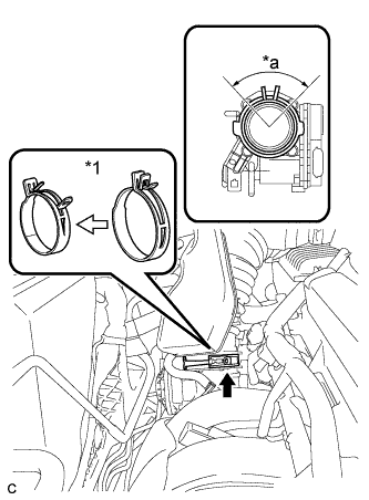
Text in Illustration *1 Air Cleaner Hose Clamp Connect the air cleaner cap sub-assembly to the throttle with motor body assembly and release the lock of the air cleaner hose clamp.
Note
-
Align the groove of the air cleaner cap sub-assembly with the tab of the throttle with motor body assembly and install the hose.
-
Make sure that the tab of the air cleaner hose clamp stays within the range shown by *a.
-
-
Connect the ventilation hose to the cylinder head cover.
-
Install the air cleaner cap sub-assembly and tighten the 2 bolts.
- Torque:
- 5.0 N*m { 51 kgf*cm, 44 in.*lbf }
-
Connect the wire harness clamp.
-
Connect the mass air flow meter connector.
-
Connect the purge line hose to the 2 clamps.
-
Connect the 2 vacuum switching valve vacuum hoses.
-
Connect the vacuum switching valve connector.
-
-
INSTALL INLET AIR CLEANER ASSEMBLY
-
Install the inlet air cleaner assembly with the 2 bolts.
- Torque:
- 8.0 N*m { 82 kgf*cm, 71 in.*lbf }
-
-
INSTALL COOL AIR INTAKE DUCT SEAL
-
Install the cool air intake duct seal with the 9 clips.
-
-
INSTALL NO. 1 ENGINE COVER SUB-ASSEMBLY
-
Install the No. 1 engine cover sub-assembly with the 2 nuts.
- Torque:
- 9.0 N*m { 92 kgf*cm, 80 in.*lbf }
-
-
INSTALL FRONT OUTER COWL TOP PANEL SUB-ASSEMBLY
-
Install the front outer cowl top panel sub-assembly with the 10 bolts.
- Torque:
- 10 N*m { 102 kgf*cm, 7 ft.*lbf }
-
Engage the 2 clamps to install the wire harness to the front outer cowl top panel sub-assembly.
-
-
INSTALL WINDSHIELD WIPER MOTOR AND LINK ASSEMBLY
-
INSTALL FRONT FENDER APRON SEAL RH
-
INSTALL ENGINE UNDER COVER RH
-
INSTALL FRONT WHEEL OPENING EXTENSION PAD RH
-
INSTALL FRONT WHEEL RH
- Torque:
- 103 N*m { 1050 kgf*cm, 76 ft.*lbf }