AIR FUEL RATIO SENSOR INSTALLATION

Tech Tips
Perform "Inspection After Repairs" after replacing the air fuel ratio sensor Click here.
-
INSTALL AIR FUEL RATIO SENSOR (for Bank 1 Sensor 1)
-
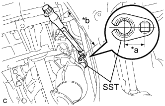
Text in Illustration *a Fulcrum Length
30 mm (1.18 in.)
*b Fulcrum Length
180 mm (7.09 in.)
Using SST, install the air fuel ratio sensor to the exhaust manifold RH.
- SST
- 09224-00010
- Torque:
- without SST
- 44 N*m { 449 kgf*cm, 33 ft.*lbf }
- with SST
- 40 N*m { 408 kgf*cm, 30 ft.*lbf }
Note
-
The "with SST" torque value is effective when using SST with a fulcrum length of 30 mm (1.18 in.) and a torque wrench with a fulcrum length of 180 mm (7.09 in.) Click here.
-
The "with SST" torque value is effective when SST is parallel to the torque wrench.
Tech Tips
Perform "Inspection After Repairs" after replacing the air fuel ratio sensor Click here.
-
Connect the harness clamp.
-
Connect the air fuel ratio sensor connector.
-
-
INSTALL FRONT EXHAUST PIPE ASSEMBLY
-
INSTALL AIR FUEL RATIO SENSOR (for Bank 2 Sensor 1)
-
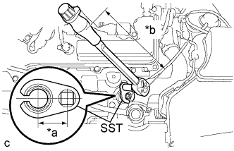
Text in Illustration *a Fulcrum Length
30 mm (1.18 in.)
*b Fulcrum Length
180 mm (7.09 in.)
Using SST, install the air fuel ratio sensor to the exhaust manifold LH.
- SST
- 09224-00010
- Torque:
- without SST
- 44 N*m { 449 kgf*cm, 33 ft.*lbf }
- with SST
- 40 N*m { 408 kgf*cm, 30 ft.*lbf }
Note
-
The "with SST" torque value is effective when using SST with a fulcrum length of 30 mm (1.18 in.) and a torque wrench with a fulcrum length of 180 mm (7.09 in.) Click here.
-
The "with SST" torque value is effective when SST is parallel to the torque wrench.
Tech Tips
Perform "Inspection After Repairs" after replacing the air fuel ratio sensor Click here.
-
Connect the air fuel ratio sensor connector.
-
Install the wire harness clamp.
-
-
INSPECT FOR EXHAUST GAS LEAK
-
INSTALL V-BANK COVER SUB-ASSEMBLY
-
Fit the 3 retainers and install the V-bank cover sub-assembly.
-
-
INSTALL COOL AIR INTAKE DUCT SEAL
-
Install the cool air intake duct seal with the 9 clips.
-