SFI SYSTEM, Diagnostic DTC:U0101

| DTC Code | DTC Name |
|---|---|
| U0101 | Lost Communication with TCM |
MONITOR DESCRIPTION
The Transmission Control Module (TCM) and ECM perform 2-way communication with each other via the Controller Area Network (CAN). The TCM sends signals to the ECM concerning required engine speed, required engine torque, warning indicators in the combination meter assembly, DTCs and other data. The ECM sends signals to the TCM concerning engine speed, opening angle of the throttle valve, temperature of intake air, temperature of engine coolant, engine torque and other data. If the TCM cannot communicate with the ECM, the TCM will conclude that there is a malfunction in the CAN system, illuminate the MIL and store a DTC.
| DTC No. | DTC Detection Condition | Trouble Area |
|---|---|---|
| U0101 |
|
|
MONITOR STRATEGY
| Required Sensors/Components | ECM |
| Frequency of Operation | Continuous |
CONFIRMATION DRIVING PATTERN
-
Connect the intelligent tester to the DLC3.
-
Turn the engine switch on (IG) and turn the tester on.
-
Clear the DTCs (even if no DTCs are stored, perform the clear DTC procedure).
-
Turn the engine switch off and wait for at least 30 seconds.
-
Turn the engine switch on (IG) and turn the tester on.
-
Wait 5 seconds or more.
-
Enter the following menus: Powertrain / Engine / DTC.
-
Read the pending DTCs.
Tech Tips
-
If a pending DTC is output, the system is malfunctioning.
-
If a pending DTC is not output, perform the following procedure.
-
-
Enter the following menus: Powertrain / Engine / Utility / All Readiness.
-
Input the DTC: U0101.
-
Check the DTC judgment result.
Tester Display Description NORMAL
-
DTC judgment completed
-
System normal
ABNORMAL
-
DTC judgment completed
-
System abnormal
INCOMPLETE
-
DTC judgment not completed
-
Perform driving pattern after confirming DTC enabling conditions
N/A
-
Unable to perform DTC judgment
-
Number of DTCs which do not fulfill DTC preconditions has reached ECU's memory limit
Tech Tips
-
If the judgment result shows NORMAL, the system is normal.
-
If the judgment result shows ABNORMAL, the system has a malfunction.
-
If the judgment result shows INCOMPLETE or N/A, perform the Confirmation Driving Pattern and check the DTC judgment result again.
-
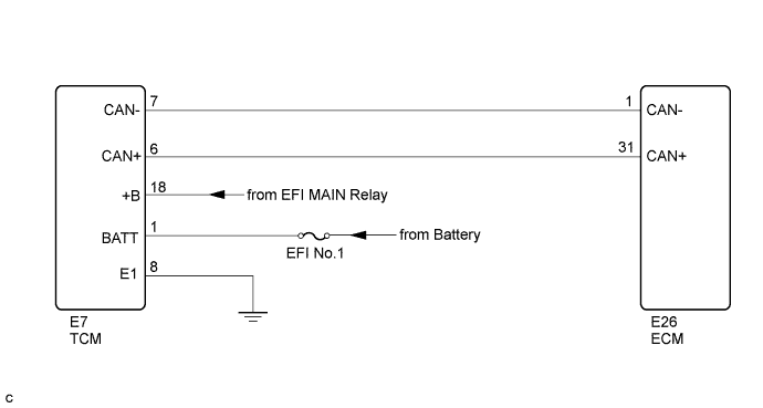
WIRING DIAGRAM
INSPECTION PROCEDURE
Read freeze frame data using the intelligent tester. The ECM records vehicle and driving condition information as freeze frame data the moment a DTC is stored. When troubleshooting, freeze frame data can help determine if the vehicle was moving or stationary, if the engine was warmed up or not, if the air fuel ratio was lean or rich, and other data from the time the malfunction occurred.
PROCEDURE
-
CHECK ANY OTHER DTCS OUTPUT (IN ADDITION TO DTC U0101)
-
Connect the intelligent tester to the DLC3.
-
Turn the engine switch on (IG).
-
Turn the tester on.
-
Enter the following menus: Powertrain / Engine / DTC.
-
Read the DTCs.
Result Result Proceed to DTC U0101 is output A DTC U0101 and other DTCs are output B Tech Tips
If any DTCs other than U0101 are output, troubleshoot those DTCs first.
B 
GO TO DTC CHART Click here
A 
-
-
CHECK TERMINAL VOLTAGE (POWER SOURCE OF TCM)
-
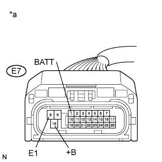
Text in Illustration *a Front view of wire harness connector
(to TCM)
Disconnect the TCM connector.
-
Turn the engine switch on (IG).
-
Measure the voltage according to the value(s) in the table below.
Standard Voltage Tester Connection Switch Condition Specified Condition E7-1 (BATT) - E7-8 (E1) Always 11 to 14 V E7-18 (+B) - E7-8 (E1) Engine switch on (IG) 11 to 14 V
NG
GO TO TCM POWER SOURCE CIRCUIT Click here
OK
-
-
CHECK HARNESS AND CONNECTOR (TCM - ECM)
-
Disconnect the TCM connector.
-
Disconnect the ECM connector.
-
Measure the resistance according to the value(s) in the table below.
Standard Resistance Tester Connection Condition Specified Condition E7-6 (CAN+) - E26-31 (CAN+) Always Below 1 Ω E7-7 (CAN-) - E26-1 (CAN-) Always Below 1 Ω E7-6 (CAN+) or E26-31 (CAN+) - Body ground Always 10 kΩ or higher E7-7 (CAN-) or E26-1 (CAN-) - Body ground Always 10 kΩ or higher
NG
REPAIR OR REPLACE HARNESS OR CONNECTOR
OK
-
-
REPLACE TCM
-
Replace the TCM Click here.
NEXT
-
-
CHECK WHETHER DTC OUTPUT RECURS (DTC U0101)
-
Connect the intelligent tester to the DLC3.
-
Turn the engine switch on (IG).
-
Turn the tester on.
-
Clear the DTCs Click here.
-
Turn the engine switch off.
-
Turn the engine switch on (IG).
-
Turn the tester on.
-
Wait for 5 seconds or more.
-
Enter the following menus: Powertrain / Engine / DTC.
-
Read the DTCs.
Result Result Proceed to DTC is not output A DTC U0101 is output B
B
REPLACE ECM Click here
A 
END
-