CAMSHAFT POSITION SENSOR INSTALLATION

-
INSTALL CAMSHAFT POSITION SENSOR
-
Clean and degrease the threads of the bolt for the camshaft position sensor.
-
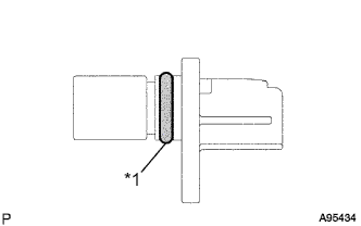
Text in Illustration *1 O-ring Apply a light coat of engine oil to the O-ring of the camshaft position sensor.
Note
Make sure that the O-ring is not cracked or moved out of place during installation.
-
Install the camshaft position sensor with the bolt.
- Torque:
- 9.0 N*m { 92 kgf*cm, 80 in.*lbf }
-
Connect the camshaft position sensor connector.
-
-
CONNECT VENTILATION HOSE
-
Connect the ventilation hose to the cylinder head cover sub-assembly.
-
-
INSTALL AIR CLEANER CAP SUB-ASSEMBLY
-
Install the air cleaner filter element to the air cleaner case sub-assembly.
-
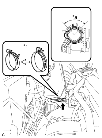
Text in Illustration *1 Air Cleaner Hose Clamp Connect the air cleaner cap sub-assembly to the throttle with motor body assembly and release the lock of the air cleaner hose clamp.
Note
-
Align the groove of the air cleaner cap sub-assembly with the tab of the throttle with motor body assembly and install the hose.
-
Make sure that the tab of the air cleaner hose clamp stays within the range shown by *a.
-
-
Connect the ventilation hose to the cylinder head cover.
-
Install the air cleaner cap sub-assembly and tighten the 2 bolts.
- Torque:
- 5.0 N*m { 51 kgf*cm, 44 in.*lbf }
-
Connect the wire harness clamp.
-
Connect the mass air flow meter connector.
-
Connect the purge line hose to the 2 clamps.
-
Connect the 2 vacuum switching valve vacuum hoses.
-
Connect the vacuum switching valve connector.
-
-
INSPECT FOR OIL LEAK
-
INSTALL NO. 1 ENGINE COVER SUB-ASSEMBLY
-
Install the No. 1 engine cover sub-assembly with the 2 nuts.
- Torque:
- 9.0 N*m { 92 kgf*cm, 80 in.*lbf }
-