МАСЛЯНЫЙ НАСОС СНЯТИЕ

-
REMOVE ENGINE ASSEMBLY WITH TRANSAXLE
-
INSTALL ENGINE STAND
-
Install the engine onto an engine stand with the bolts.
-
-
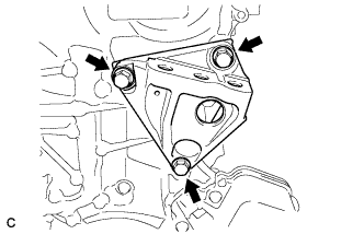
REMOVE ENGINE HANGERS
-

Remove the 2 bolts and 2 engine hangers.
-
-
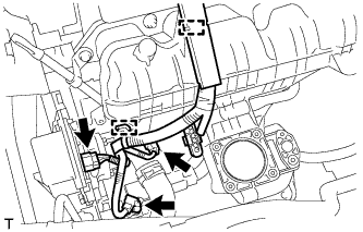
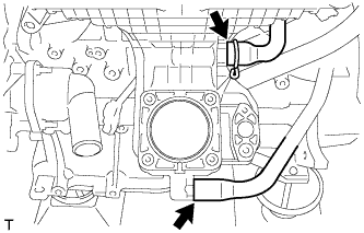
REMOVE THROTTLE BODY ASSEMBLY
-
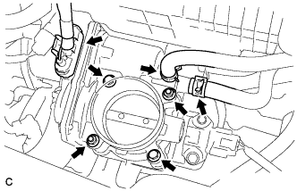
Отсоедините разъем корпуса дроссельной заслонки и 2 перепускных шланга охлаждающей жидкости.
-
Выверните 2 болта, отверните 2 гайки и снимите корпус дроссельной заслонки в сборе.
-
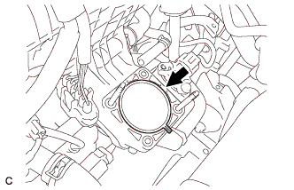
Снимите прокладку с впускного коллектора.
-
-
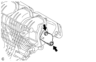
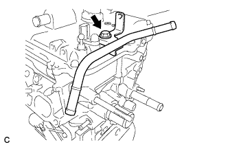
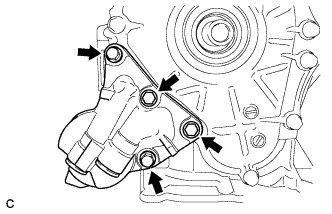
REMOVE ENGINE OIL LEVEL DIPSTICK GUIDE
-
Remove the engine oil level dipstick.
-
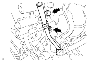
Remove the 2 bolts, clamp and engine oil level dipstick guide.
-
Remove the O-ring from the engine oil level dipstick guide.
-
-
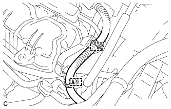
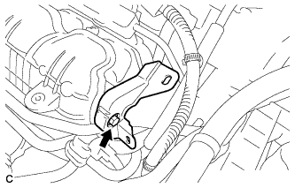
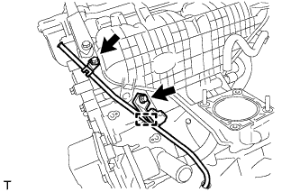
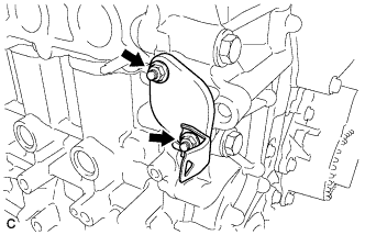
REMOVE WATER BY-PASS PIPE
-
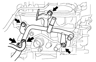
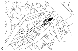
Disconnect the 2 water hoses.
-
Remove the 2 bolts, nut and water by-pass pipe.
-
-
REMOVE INTAKE MANIFOLD
-
Disconnect the 2 wire harness clamps.
-
Remove the bolt and wire harness support.
-
Remove the 2 bolts and surge tank cover.
-
Remove the gasket from the intake manifold.
-
Disconnect the 3 connectors and 2 wire harness clamps.
-
Remove the engine oil level dipstick.
-
Disconnect the wire harness clamp, and then remove the 2 bolts and engine oil level dipstick guide sub-assembly.
-
Remove the O-ring from the engine oil level dipstick guide sub-assembly.
-
Disconnect the fuel vapor feed hose and ventilation hose.
-
Remove the 2 bolts, 2 nuts and intake manifold.
-
Remove the No. 1 intake manifold to head gasket.
-
-
REMOVE FUEL VAPOR FEED PIPE
-
Remove the bolt and fuel vapor feed pipe.
-
-
REMOVE FUEL DELIVERY PIPE SUB-ASSEMBLY
-
Remove the bolt.
-
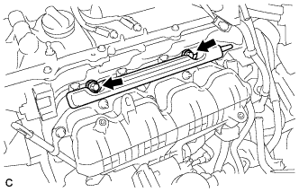
Remove the 2 bolts and fuel delivery pipe sub-assembly.
Note
Be careful not to drop the fuel injectors when removing the fuel delivery pipe.
-
-
REMOVE NO. 1 DELIVERY PIPE SPACER
-
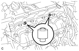
Remove the 2 delivery pipe spacers from the cylinder head.
-
-
REMOVE FUEL INJECTOR ASSEMBLY
-
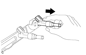
Pull the 4 fuel injector assemblies out of the fuel delivery pipe sub-assembly.
-
Remove the O-ring from each fuel injector assembly.
-
For reinstallation, attach a tag or label to each injector shaft.
Note
Prevent entry of foreign objects by covering the fuel injectors with plastic bags.
-
Remove the 4 injector vibration insulators.
-
-
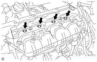
REMOVE IGNITION COIL ASSEMBLY
-
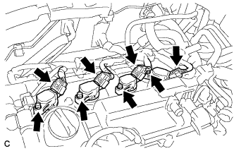
Отсоедините разъемы 4 катушек зажигания.
-
Выверните 4 болта и снимите 4 катушки зажигания.
Note
При снятии катушек зажигания соблюдайте осторожность, чтобы не повредить наконечники свечей зажигания о края отверстия в крышке головки блока цилиндров или верхнюю кромку трубки свечного колодца.
-
-
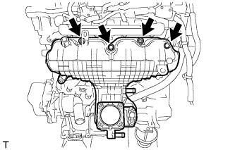
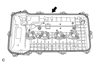
REMOVE CYLINDER HEAD COVER SUB-ASSEMBLY
-
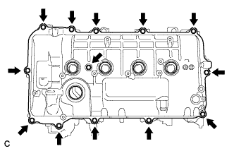
Выверните 13 болтов и снимите крышку головки блока цилиндров с уплотнительной шайбой.
Note
Соблюдайте осторожность, чтобы не уронить прокладки в двигатель при снятии крышки головки блока цилиндров, поскольку прокладки могут прилипнуть к крышке.
-
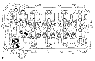
Снимите 2 прокладки с крышки подшипника распредвала.
-
-
REMOVE CYLINDER HEAD COVER GASKET
-
Снимите прокладку крышки головки блока цилиндров.
-
-
REMOVE SPARK PLUG TUBE GASKET
-
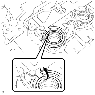
Отожмите 4 захвата отражающей вентиляционной заслонки.
Note
Не деформируйте захваты вентиляционной заслонки больше, чем необходимо.
-
Снимите 4 прокладки с крышки головки блока цилиндров.
Tech Tips
Постарайтесь как можно меньше деформировать прокладки трубок свечных колодцев. Снятые прокладки будут использоваться при установке новых прокладок.
Note
Будьте осторожны, чтобы не повредить крышку головки блока цилиндров.
-
-
SET NO. 1 CYLINDER TO TDC / COMPRESSION
-
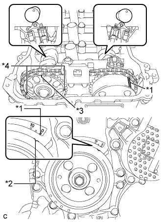
Text in Illustration *1 Timing Mark *2 Timing Notch *3 Timing Mark (Rectangle) *4 Mark (Circle) Turn the crankshaft pulley until its notch and timing mark "0" of the timing chain cover are aligned.
Tech Tips
There are 3 marks on the camshaft timing sprocket. Make sure that the timing mark (rectangle) is at the top.
-
Check that the timing marks on both the camshaft timing sprocket and the camshaft timing gear are facing upward as shown in the illustration.
If not, turn the crankshaft 1 complete revolution (360°) and align the marks as above.
-
-
REMOVE CRANKSHAFT PULLEY
-
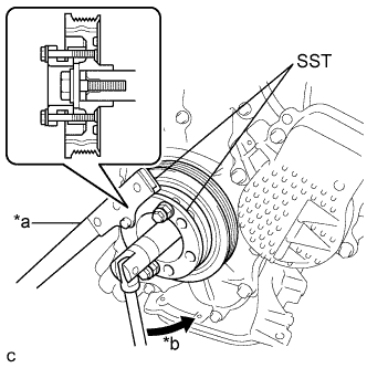
Обозначения на рисунке *a Удерживайте *b Поверните С помощью SST зафиксируйте шкив на месте и ослабьте болт шкива.
- SST
- 09213-58014 ( 91551-80840 )
- 09330-00021
-
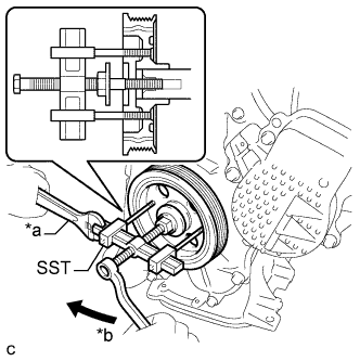
Обозначения на рисунке *a Удерживайте *b Поверните С помощью SST выверните болт шкива и снимите шкив коленчатого вала.
- SST
- 09950-50013 ( 09951-05010, 09952-05010, 09953-05020, 09954-05021 )
-
-
REMOVE NO. 1 CHAIN TENSIONER ASSEMBLY
-
Remove the 2 nuts, bracket, chain tensioner and gasket.
Note
Do not turn the crankshaft without the No. 1 chain tensioner installed.
-
-
REMOVE TIMING CHAIN COVER SUB-ASSEMBLY
-
Remove the 3 bolts and engine mounting bracket RH.
-
Remove the 4 bolts and oil filter bracket.
-
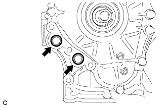
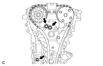
Remove the 2 O-rings.
-
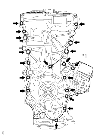
Text in Illustration *1 Seal Washer Remove the 18 bolts and seal washer.
-
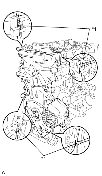
Text in Illustration *1 Protective Tape Remove the timing chain cover by prying between the timing chain cover and cylinder head or cylinder block with a screwdriver.
Note
-
Be careful not to damage the contact surfaces of the timing chain cover, cylinder block, and cylinder head.
-
Pry the timing chain cover out evenly in order to prevent damaging the knock pins.
Tech Tips
Tape the screwdriver tip before use.
-
-
Remove the 3 O-rings.
-
-
REMOVE TIMING CHAIN COVER OIL SEAL
-
Place the timing chain cover on wooden blocks.
-
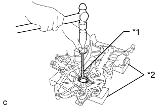
Text in Illustration *1 Protective Tape *2 Wooden Block Using a screwdriver and hammer, knock out the oil seal.
Tech Tips
Tape the screwdriver tip before use.
Note
Do not damage the surface of the oil seal press fit hole.
-
-
REMOVE CHAIN TENSIONER SLIPPER
-
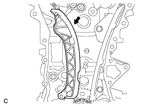
Remove the chain tensioner slipper from the cylinder block.
-
-
REMOVE NO. 1 CHAIN VIBRATION DAMPER
-
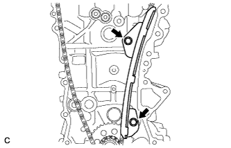
Remove the 2 bolts and chain vibration damper.
-
-
REMOVE NO. 2 CHAIN VIBRATION DAMPER
-
Remove the 2 bolts and No. 2 chain vibration damper.
-
-
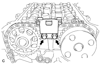
REMOVE CHAIN SUB-ASSEMBLY
-
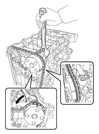
Hold the hexagonal portion of the camshaft with a wrench and turn the camshaft timing gear counterclockwise to loosen the chain between the camshaft timing gears.
-
With the chain loosened, release the chain from the camshaft timing gear and place it on the camshaft timing gear.
Tech Tips
Be sure to release the chain from the sprocket completely.
-
Turn the camshaft clockwise to return it to the original position and remove the chain.
-
-
REMOVE CRANKSHAFT TIMING SPROCKET
-
Remove the crankshaft timing sprocket.
-
-
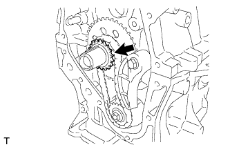
REMOVE NO. 2 CHAIN SUB-ASSEMBLY
-
Temporarily tighten the crankshaft pulley and crankshaft pulley bolt.
-
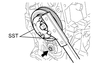
Using SST, remove the oil pump drive shaft sprocket nut while holding the crankshaft pulley.
- SST
- 09213-58014 ( 91551-80840 )
- 09330-00021
-
Remove SST, the crankshaft pulley and crankshaft pulley bolt.
-
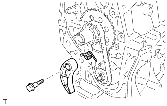
Remove the bolt, chain tensioner plate and chain damper spring.
-
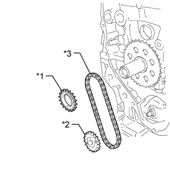
Text in Illustration *1 Oil Pump Drive Gear *2 Oil Pump Drive Shaft Gear *3 No. 2 Chain Sub-assembly Remove the oil pump drive gear, oil pump drive shaft gear and No. 2 chain sub-assembly.
-
-
REMOVE NO. 1 CRANKSHAFT POSITION SENSOR PLATE
-
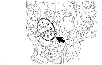
Снимите зубчатый диск датчика положения коленчатого вала.
-
-
REMOVE CRANKSHAFT TIMING GEAR KEY
-
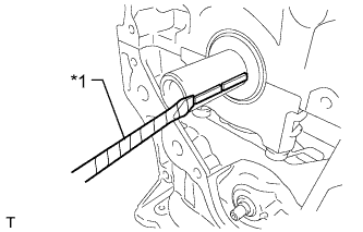
Обозначения на рисунке *1 Защитная клейкая лента С помощью отвертки снимите 2 шпонки ведущего зубчатого колеса привода ГРМ с коленчатого вала
Tech Tips
Конец отвертки перед использованием следует изолировать защитной клейкой лентой.
-
-
REMOVE OIL PAN DRAIN PLUG
-
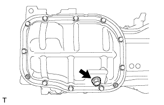
Выверните пробку сливного отверстия и снимите прокладку.
-
-
REMOVE NO. 2 OIL PAN SUB-ASSEMBLY
-
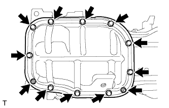
Remove the 10 bolts and 2 nuts.
-
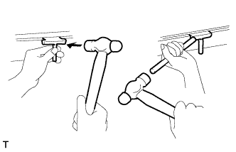
Insert the blade of an oil pan seal cutter between the crankcase and oil pan. Cut through the sealer and remove the oil pan.
Note
Be careful not to damage the contact surfaces of the crankcase, chain cover and oil pan.
-
-
REMOVE OIL PUMP ASSEMBLY
-
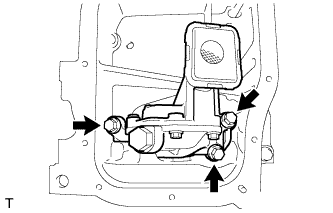
Remove the 3 bolts and oil pump.
-