ВЫПУСКНОЙ КОЛЛЕКТОР УСТАНОВКА

-
INSTALL NO. 2 EXHAUST MANIFOLD HEAT INSULATOR
-

Install the No. 2 exhaust manifold heat insulator with the 3 bolts.
- Torque:
- 12 N*m { 122 kgf*cm, 9 ft.*lbf }
-
-
INSTALL EXHAUST MANIFOLD
-
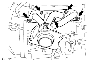
Install a new gasket and the exhaust manifold with the 5 nuts.
- Torque:
- 21 N*m { 214 kgf*cm, 15 ft.*lbf }
-
-
INSTALL MANIFOLD STAY
-
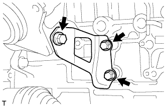
Install the manifold stay with the 3 bolts.
- Torque:
- 43 N*m { 438 kgf*cm, 32 ft.*lbf }
-
-
INSTALL AIR FUEL RATIO SENSOR
-
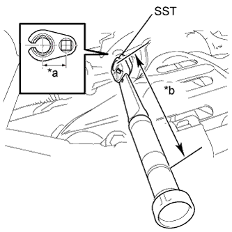
Text in Illustration *a Fulcrum Length
30 mm
*b Fulcrum Length
300 mm
Using SST, install the air fuel ratio sensor.
- SST
- 09224-00010
- Torque:
- without SST
- 44 N*m { 449 kgf*cm, 32 ft.*lbf }
- with SST
- 40 N*m { 408 kgf*cm, 30 ft.*lbf }
Note
-
The "with SST" torque value is effective when using SST with a fulcrum length of 30 mm (1.18 in.) and a torque wrench with a fulcrum length of 300 mm (11.8 in.) Click here.
-
The "with SST" torque value is effective when SST is parallel to the torque wrench.
-
Connect the air fuel ratio sensor connector and clamp.
-
-
INSTALL NO. 1 EXHAUST MANIFOLD HEAT INSULATOR
-
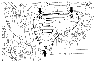
Install the No. 1 exhaust manifold heat insulator with the 3 bolts.
- Torque:
- 12 N*m { 122 kgf*cm, 9 ft.*lbf }
-
-
INSTALL FRONT NO. 1 FLOOR HEAT INSULATOR
-

Install the No. 1 floor heat insulator with the 3 nuts.
- Torque:
- 5.5 N*m { 56 kgf*cm, 49 in.*lbf }
-
-
INSTALL FRONT EXHAUST PIPE ASSEMBLY
-
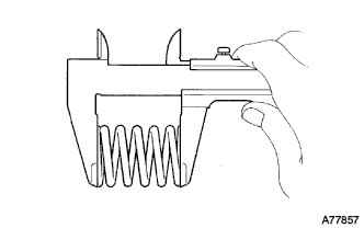
Using a vernier caliper, measure the free length of the compression springs.
Minimum (front) 41.5 mm (1.64 in.) Minimum (rear) 38.5 mm (1.52 in.) Tech Tips
If the free length is less than minimum, replace the compression spring.
-
Fully insert 2 new gaskets to the exhaust manifold and front exhaust pipe assembly.
-
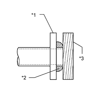
Text in Illustration *1 Exhaust Manifold and Front Exhaust Pipe Assembly *2 Gasket *3 Wooden Block Using a plastic hammer and wooden block, tap in each new gasket until its surface is flush with the exhaust manifold and front exhaust pipe assembly.
Note
-
Be careful with the installation direction of the gaskets.
-
Do not reuse the gaskets.
-
Do not damage the gaskets.
-
Do not push in the gasket by using the exhaust pipe when connecting it.
-
-
Connect the front exhaust pipe assembly to the 2 exhaust pipe supports.
-
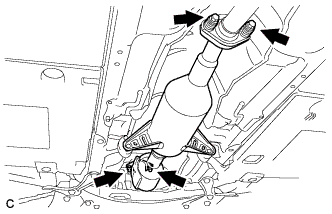
Install the front exhaust pipe assembly with the 4 bolts and 4 compression springs.
- Torque:
- 43 N*m { 438 kgf*cm, 32 ft.*lbf }
-
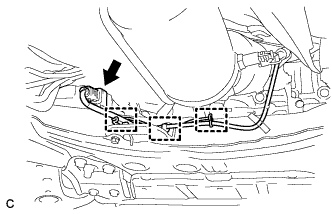
Connect the 3 clamps and oxygen sensor connector.
-
-
INSTALL FRONT CENTER FLOOR BRACE
-
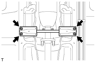
Установите центральный передний подкос пола и закрепите его 4 болтами.
- Torque:
- 51 Н*м { 520 кгс*см, 38 фунт-сила-футов }
-
-
INSTALL FRONT NO. 3 ENGINE UNDER COVER
-
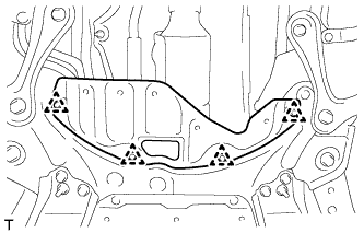
Установите переднюю защиту картера двигателя № 3 и закрепите ее 4 фиксаторами.
-
-
INSTALL NO. 1 ENGINE UNDER COVER
-
INSTALL NO. 2 CYLINDER HEAD COVER
-
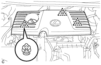
Установите крышку, закрепив ее 3 фиксаторами.
Note
-
Проверьте надежность зацепления фиксаторов.
-
Во время зацепления фиксаторов на крышке не прикладывайте чрезмерных усилий и не допускайте ударов. Это может привести к поломке крышки.
-
-
-
INSTALL OUTER COWL TOP PANEL SUB-ASSEMBLY
-
Установите наружную верхнюю панель кожуха в сборе и закрепите ее 9 болтами.
- Torque:
- 12 Н*м { 122 кгс*см, 9 фунт-сила-футов }
-
Для моделей с противообледенителем стеклоочистителя:
Установите жгут проводов и введите в зацепление 3 зажима.
-
Введите в зацепление зажим, чтобы закрепить жгут проводов.
-
-
INSTALL COWL BODY MOUNTING REINFORCEMENT LH
-
Установите левый усилитель крепления кожуха к кузову и закрепите его 2 болтами.
- Torque:
- 12 Н*м { 122 кгс*см, 9 фунт-сила-футов }
-
-
INSTALL NO. 2 HEATER AIR DUCT SPLASH SHIELD SEAL
-
Введите в зацепление захват и направляющую, чтобы установить брызгозащитное уплотнение воздуховода отопителя № 2.
-
-
REMOVE NO. 1 HEATER AIR DUCT SPLASH SHIELD SEAL
-
Введите в зацепление 2 захвата, чтобы закрепить брызгозащитное уплотнение воздуховода отопителя № 1.
-
-
INSTALL WINDSHIELD WIPER MOTOR AND LINK ASSEMBLY
-
INSPECT FOR EXHAUST GAS LEAK