ТОПЛИВНЫЙ БАК УСТАНОВКА
-
INSTALL FUEL TANK COVER VENT CASE SUB-ASSEMBLY
-
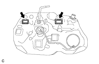
Install 2 new fuel tank cover vent case sub-assemblies as shown in the illustration.
-
-
INSTALL NO. 1 FUEL TANK CUSHION
-
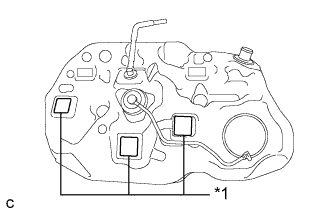
Text in Illustration *1 No. 1 Fuel Tank Cushion Install 3 new No. 1 fuel tank cushions as shown in the illustration.
-
-
INSTALL NO. 1 CHARCOAL CANISTER OUTLET HOSE
-
Install the hose clamp and the No. 1 charcoal canister outlet hose to the fuel tank.
-
-
INSTALL FUEL TANK ASSEMBLY
-
Support the fuel tank using an engine lifter.
-
Raise the engine lifter, then install the fuel tank to the vehicle.
Note
-
Do not drop the fuel tank.
-
When installing the fuel tank, tilt it slightly to prevent it from interfering with the suspension arm or other surrounding parts.
-
-
Tighten the 4 set bolts of the 2 fuel tank bands.
- Torque:
- 45 N*m { 459 kgf*cm, 33 ft.*lbf }
-
Connect the parking brake cable assembly with the 2 bolts.
- Torque:
- 6.0 N*m { 61 kgf*cm, 53 in.*lbf }
-
-
CONNECT FUEL TANK MAIN TUBE SUB-ASSEMBLY
-
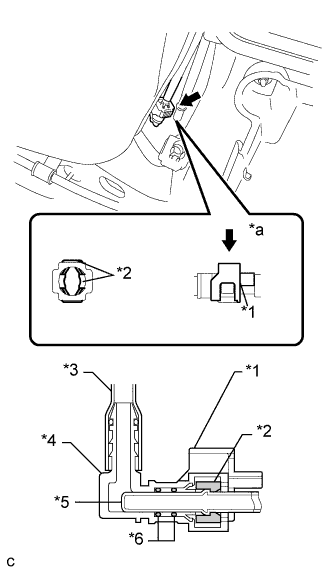
Text in Illustration *1 Fuel Tube Connector Cover *2 Retainer *3 Nylon Tube *4 Fuel Tube Connector *5 Fuel Pipe *6 O-ring *a Push Align the fuel tube connector with the fuel pipe, push the fuel tube connector in until the retainer makes a "click" sound, then lock the fuel tube connector cover of the fuel tube connector.
Note
-
Check that there are no scratches or foreign matter around the connected parts of the fuel tube connector and fuel pipe before performing this work.
-
After connecting the fuel tank main tube sub-assembly, check that the fuel tank main tube sub-assembly is securely connected by pulling on the fuel tube connector.
-
-
-
CONNECT NO. 1 FUEL EVAPORATION TUBE SUB-ASSEMBLY
-
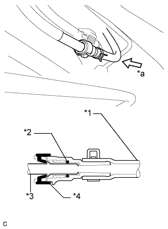
Text in Illustration *1 Rubber Hose *2 O-ring *3 Fuel Pipe *4 Retainer *a Push Push in the tube connector to the fuel pipe and install the retainer.
Note
-
Check if there is any damage or foreign matter on the connected parts of the fuel pipe.
-
After connecting the fuel tube connector and pipe, check if they are securely connected by pulling on them.
-
-
-
CONNECT FUEL TANK TO FILLER PIPE HOSE
-
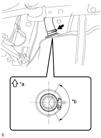
Text in Illustration *a Upper Side *b 120° Connect the fuel tank to filler pipe hose to the fuel tank as shown in the illustration, then fit the hose with the clamp.
-
-
CONNECT FUEL TANK BREATHER TUBE
-
Connect the fuel tank breather tube to the fuel tank.
-
Connect the No. 1 charcoal canister outlet hose.
Note
After connecting the breather tube and No. 1 charcoal canister outlet hose, check that the evaporation vent tube clamp is securely connected to the fuel tank.
-
-
INSTALL NO. 1 FUEL TANK PROTECTOR
-
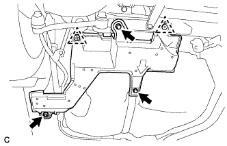
Install the No. 1 fuel tank protector with the 2 bolts and nut.
- Torque:
- 5.5 N*m { 56 kgf*cm, 49 in.*lbf }
-
-
INSTALL REAR FLOOR SIDE MEMBER COVER LH
-
Install the rear floor side member cover LH with the 2 clips.
-
Install the 2 bolts and nut.
-
-
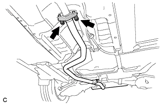
INSTALL TAIL EXHAUST PIPE ASSEMBLY
-
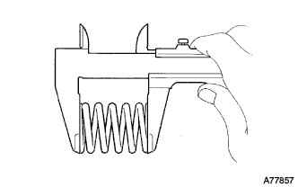
При помощи штангенциркуля замерьте длину пружины сжатия в свободном состоянии.
Минимальное значение 38,5 мм (1,52 дюйма) Tech Tips
Если свободная длина меньше минимально допустимой, замените пружину сжатия.
-
Полностью вставьте новую прокладку в приемную трубу в сборе.
-
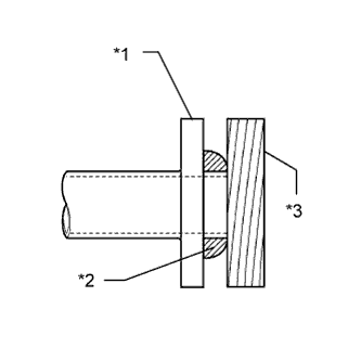
Обозначения на рисунке *1 Приемная труба в сборе *2 Прокладка *3 Деревянный брусок С помощью пластмассового молотка и деревянного бруска запрессовывайте новую прокладку до тех пор, пока ее поверхность не окажется на одном уровне с приемной трубой в сборе.
Note
-
Правильно выберите направление установки прокладки.
-
Повторное использование прокладок запрещено.
-
Действуйте осторожно, чтобы не повредить прокладку.
-
Старайтесь не нажимать на прокладку выпускной трубой при соединении.
-
-
Подсоедините заднюю выпускную трубу в сборе к 3 опорам выпускной трубы.
-
Установите заднюю выпускную трубу в сборе и закрепите ее 2 пружинами сжатия и 2 болтами.
- Torque:
- 43 Н*м { 438 кгс*см, 32 фунт-сила-фута }
-
-
ADD FUEL
-
INSTALL FUEL SUCTION TUBE WITH PUMP AND GAUGE ASSEMBLY
-
INSPECT FOR EXHAUST GAS LEAK