ТОПЛИВНЫЙ НАСОС УСТАНОВКА

-
INSTALL FUEL SUCTION TUBE WITH PUMP AND GAUGE ASSEMBLY
-
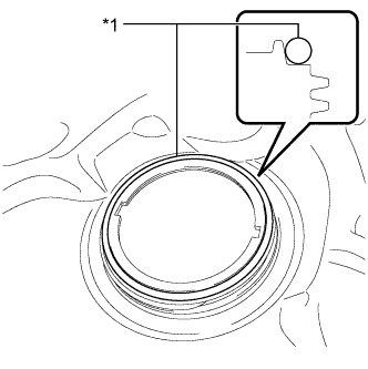
Text in Illustration *1 Gasket Install a new gasket onto the fuel tank.
-
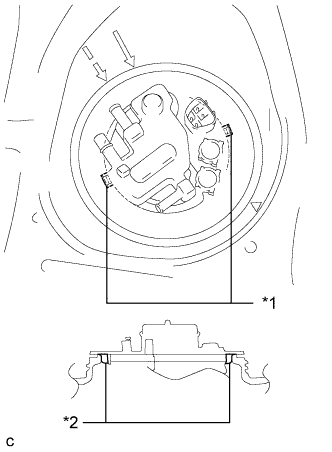
Text in Illustration *1 Notch *2 Protrusion Set the fuel suction tube with pump and gauge assembly to the fuel tank.
Note
Make sure that the fuel sender gauge arm does not bend.
-
Align the protrusions of the fuel suction tube with pump and gauge assembly with the notches of the fuel tank.
-
-
INSTALL FUEL PUMP GAUGE RETAINER
-
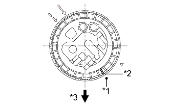
Text in Illustration *1 Start Mark *2 Mark *3 Front While holding the fuel suction tube with pump and gauge assembly by hand to prevent it from tilting, align the mark on the new fuel pump gauge retainer with the start mark on the fuel tank and tighten the fuel pump gauge retainer 180° by hand.
Tech Tips
-
Check that there is no damage, dents, foreign matter or other defects on the threads of the fuel tank.
-
-
Text in Illustration *1 SST
(Plate)
*2 SST
(Claw)
*3 Rib Temporarily install the SST plate and claws to the fuel pump gauge retainer.
- SST
- 09808-14030 ( 09808-01030, 09808-01040, 09808-01050 )
Tech Tips
Engage the SST claws securely with the fuel pump gauge retainer ribs to secure SST.
-
While pressing the claws of SST to the fuel pump gauge retainer ribs securely, tighten the bolts.
Tech Tips
Install SST while pressing the SST claws toward the fuel pump gauge retainer (toward the center of SST).
-
Install the SST handle.
-
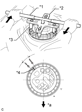
Text in Illustration *1 SST
(Handle)
*2 SST
(Plate)
*3 SST
(Claw)
*4 Mark *a Front Side Tighten the fuel pump gauge retainer approximately 360° so that the mark on the retainer comes within the range shown in the illustration.
- SST
- 09808-14030 ( 09808-01010, 09808-01020, 09808-01030, 09808-01040, 09808-01050 )
Note
-
Do not use any tools other than specified in this operation. Damage to the fuel pump gauge retainer or the fuel tank may result.
-
Do not press down on SST excessively as this may make the retainer hard to rotate, and may damage components.
-
Make sure to rotate the SST handle horizontally. If the SST handle is rotated at an angle, SST may come off.
-
Do not spin SST too fast or use an impact wrench as this may result in damage to components.
-
If SST comes off of the retainer, loosen the SST bolts and reinstall SST.
Tech Tips
-
Lightly press down on SST to prevent it from separating from the retainer. While pressing SST, rotate the handle slowly to tighten the retainer.
-
The ribs on the fuel pump gauge retainer can be fitted into the tips of SST.
-
-
CONNECT FUEL TANK EVAPORATION TUBE
-
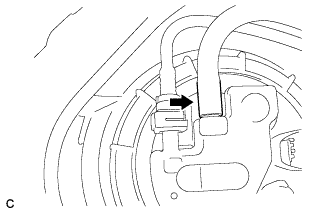
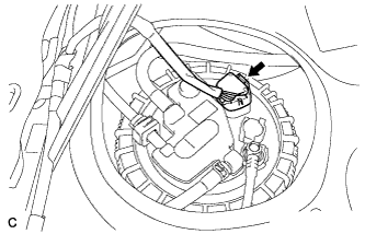
Text in Illustration *1 Retainer Connect the fuel tank evaporation tube to the fuel suction tube with pump and gauge assembly.
-
-
CONNECT NO. 1 CHARCOAL CANISTER OUTLET HOSE
-
Connect the No. 1 charcoal canister outlet hose to the fuel suction tube with pump and gauge assembly.
Tech Tips
After connecting the No. 2 fuel tank evaporation tube and No. 1 charcoal canister outlet hose, check that the No. 2 fuel tank evaporation tube is positioned below the No. 1 charcoal canister outlet hose.
-
-
CONNECT NO. 1 FUEL EVAPORATION TUBE SUB-ASSEMBLY
-
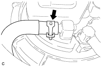
Connect the No. 1 fuel evaporation tube sub-assembly to the fuel suction tube with pump and gauge assembly with the clip.
-
-
CONNECT FUEL TANK MAIN TUBE SUB-ASSEMBLY
-
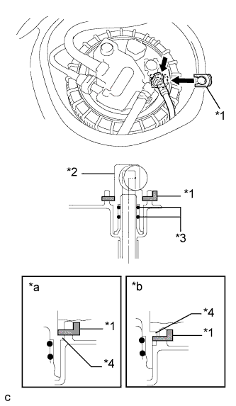
Text in Illustration *1 Tube Joint Clip *2 Fuel Tube Joint *3 O-ring *4 Collar *a CORRECT *b INCORRECT Push the fuel tube joint in the plug of the fuel suction plate, then install the tube joint clip.
Note
-
Check that there are no scratches or foreign matter around the connected part of the fuel tube joint and plug before performing this work.
-
Check that the fuel tube joint is securely inserted to the end.
-
Check that the tube joint clip is on the collar of the fuel tube joint.
-
After installing the tube joint clip, check that the fuel tank main tube cannot be pushed out.
-
-
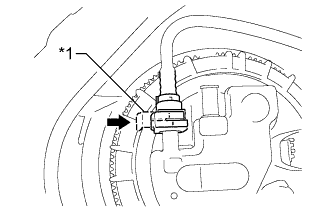
Connect the fuel pump connector.
-
-
CONNECT CABLE TO NEGATIVE AUXILIARY BATTERY TERMINAL
Note
When disconnecting the cable, some systems need to be initialized after the cable is reconnected Click here.
-
INSPECT FOR FUEL LEAK
-
Check fuel pump operation.
-
Connect the intelligent tester to the DLC3.
-
Turn the power switch on (IG).
Note
Do not start the engine.
-
Turn the intelligent tester on.
-
Enter the following menus: Powertrain / Engine and ECT / Active Test / Control the Fuel Pump / Speed.
-
Check for pressure in the fuel inlet tube from the fuel line. Check that sounds of fuel flowing from the fuel tank can be heard. If no sounds can be heard, check the integration relay, fuel pump, ECM and wiring connectors.
-
-
Inspect for fuel leaks.
-
Check that there are no fuel leaks after performing maintenance anywhere on the fuel system. If there are fuel leaks, repair or replace parts as necessary.
-
-
Turn the power switch off.
-
Disconnect the intelligent tester from the DLC3.
-
-
INSTALL REAR FLOOR SERVICE HOLE COVER
-
Install the rear floor service hole cover with new butyl tape.
-
-
INSTALL REAR SEAT CUSHION LOCK HOOK
-
Установите новое крепление подушки заднего сиденья и закрепите его захватом.
Note
Крепления подушки заднего сиденья не подлежат повторному использованию.
Tech Tips
Порядок выполнения работ для левой и правой сторон одинаков.
-
-
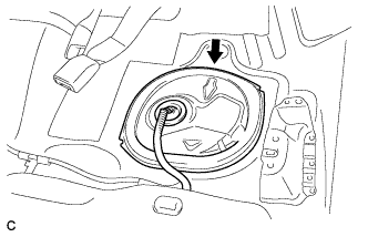
INSTALL REAR SEAT CUSHION ASSEMBLY
-
Поместите подушку заднего сиденья в сборе в салон.
Note
Соблюдайте осторожность, чтобы не повредить кузов автомобиля.
-
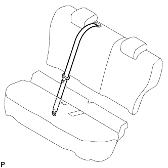
Пропустите центральный задний ремень безопасности в сборе через подушку заднего сиденья в сборе.
-
Закрепите центральный задний ремень безопасности в сборе с помощью болта.
- Torque:
- 42 Н*м { 428 кгс*см, 31 фунт-сила-фут }
-
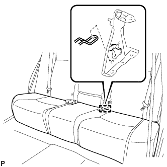
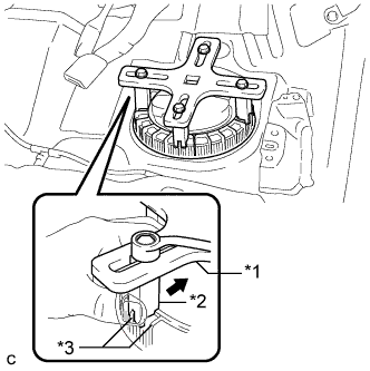
Введите в зацепление направляющую, как показано на рисунке.
-
Пропустите левый замок ремня безопасности заднего сиденья с центральным ремнем в сборе и замок ремня безопасности заднего сиденья в сборе через подушку заднего сиденья в сборе, как показано на рисунке.
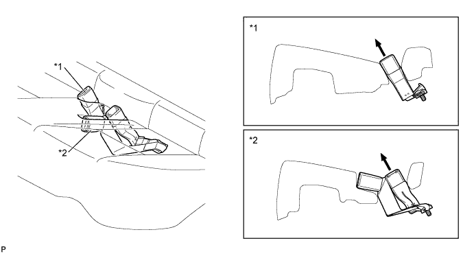
Обозначения на рисунке *1 Замок ремня безопасности заднего сиденья в сборе *2 Левый замок ремня безопасности заднего сиденья с центральным ремнем в сборе -
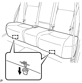
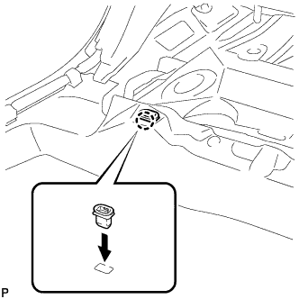
Закрепите 2 крепления подушки сиденья на кузове автомобиля, как показано на рисунке.
-
Убедитесь, что подушка сиденья установлена надежно.
Note
При установке подушки сиденья следите за тем, чтобы пряжки ремней безопасности на оказалась под подушкой сиденья.
-
-
INSTALL REAR FLOOR BOARD UPPER NO. 3 PLATE
-
Установите верхнюю пластину панели заднего пола № 3 и введите в зацепление 4 захвата и 2 направляющих.
-
-
INSTALL DECK FLOOR BOX RH
-
Введите в зацепление 6 направляющих.
-
Установите правую напольную коробку полки багажного отделения и закрепите ее фиксатором.
-
-
INSTALL REAR NO. 3 FLOOR BOARD
-
Установите панель заднего пола № 3.
-
-
INSTALL REAR DECK FLOOR BOX
-
Установите заднюю напольную коробку полки багажного отделения.
-
-
INSTALL REAR NO. 2 FLOOR BOARD
-
Установите панель заднего пола № 2.
-