ТОПЛИВНАЯ ФОРСУНКА УСТАНОВКА
-
INSTALL FUEL INJECTOR ASSEMBLY
-
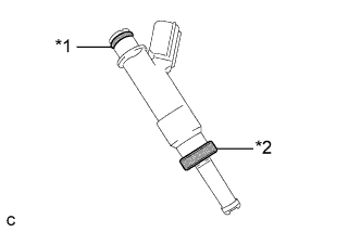
Text in Illustration *1 O-ring *2 Injector Vibration Insulator Install a new injector vibration insulator and O-ring to each fuel injector assembly.
-
Apply a light coat of gasoline or spindle oil to the contact surfaces of the new O-ring on each fuel injector assembly.
-
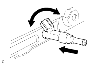
While turning the fuel injector assembly left and right, install it onto the fuel delivery pipe sub-assembly.
Note
-
Do not damage the fuel injector assembly or O-ring.
-
Do not twist the O-ring.
-
After installing each fuel injector, check that it turns smoothly. If not, replace the O-ring with a new one.
-
-
-
INSTALL NO. 1 DELIVERY PIPE SPACER
-
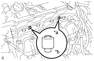
Text in Illustration *a Delivery Pipe Side *b Cylinder Head Side Install the 2 No. 1 delivery pipe spacers onto the cylinder head.
Note
Install the No. 1 delivery pipe spacers in the correct direction.
-
-
INSTALL FUEL DELIVERY PIPE SUB-ASSEMBLY
-
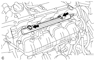
Install the fuel delivery pipe sub-assembly with the 4 fuel injector assemblies and install the 2 bolts.
- Torque:
- 21 N*m { 214 kgf*cm, 15 ft.*lbf }
Note
-
Do not drop the fuel injectors when installing the fuel delivery pipe sub-assembly.
-
Check that the fuel injector assemblies rotate smoothly after installing the fuel delivery pipe sub-assembly.
-
Install the bolt to secure the fuel delivery pipe sub-assembly.
- Torque:
- 21 N*m { 214 kgf*cm, 15 ft.*lbf }
-
-
INSTALL WATER BY-PASS PIPE
-
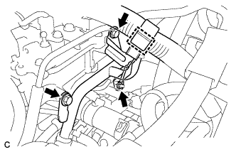
Install the water by-pass pipe with the 2 bolts and nut.
- Torque:
- 21 N*m { 214 kgf*cm, 15 ft.*lbf }
-
Engage the clamp to connect the wire harness.
-
-
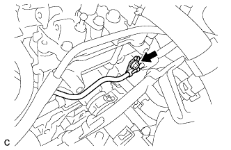
CONNECT FUEL TUBE SUB-ASSEMBLY
-
Push the fuel tube connector to the fuel pipe until the fuel tube connector makes a "click" sound.
Note
-
Before connecting the fuel tube connector and fuel pipe, check that there is no damage or foreign matter on the connecting part of the fuel pipe.
-
After connecting the fuel tube connector and fuel pipe, check that they are securely connected by trying to pull them apart.
-
-
Engage the lock claw to install the No. 1 fuel pipe clamp.
-
-
CONNECT ENGINE WIRE
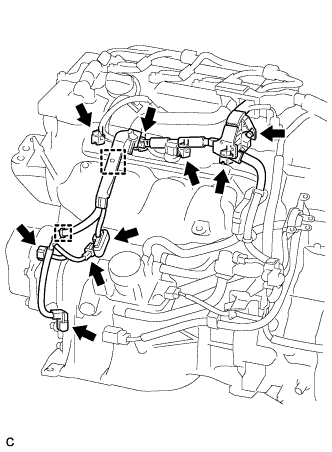
-
Install the bolt.
- Torque:
- 8.3 N*m { 85 kgf*cm, 73 in.*lbf }
-
Connect the 4 fuel injector connectors.
-
Connect the 4 connectors.
-
Attach the 2 clamps to connect the wire harness.
-
-
INSTALL AIR CLEANER HOSE ASSEMBLY
-
Установите шланг воздушного фильтра в сборе и зафиксируйте зажим шланга.
-
Подключите вентиляционный шланг.
-
-
INSTALL AIR CLEANER CASE
-
Установите корпус воздушного фильтра и закрепите его 2 болтами.
- Torque:
- 7,0 Н*м { 71 кгс*см, 62 фунт-сила-дюйма }
-
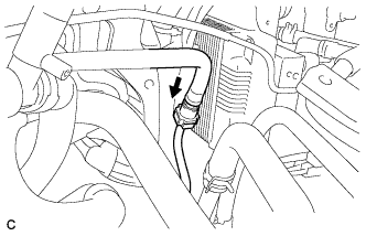
Закрепите шланг охлаждающей жидкости зажимом.
-
Установите фильтрующий элемент воздушного фильтра в сборе.
-
-
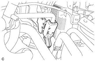
INSTALL INLET AIR CLEANER ASSEMBLY
-
Установите входной патрубок воздушного фильтра на корпус фильтра.
-
Закрепите входной патрубок воздушного фильтра 2 болтами и 2 фиксаторами.
- Torque:
- 7,0 Н*м { 71 кгс*см, 62 фунт-сила-дюйма }
-
Подсоедините зажим жгута проводов к входному патрубку воздушного фильтра в сборе.
-
Закрепите шланг охлаждающей жидкости зажимом.
-
-
INSTALL AIR CLEANER CAP SUB-ASSEMBLY
-
Закрепите крышку воздушного фильтра в сборе 2 зажимами.
-
Затяните хомут шланга.
-
Подключите разъем датчика массового расхода воздуха.
-
Присоедините зажим жгута проводов.
-
-
CONNECT CABLE TO NEGATIVE AUXILIARY BATTERY TERMINAL
Note
When disconnecting the cable, some systems need to be initialized after the cable is reconnected Click here.
-
INSPECT FOR FUEL LEAK
-
Check fuel pump operation.
-
Connect the intelligent tester to the DLC3.
-
Turn the power switch on (IG).
Note
Do not start the engine.
-
Turn the intelligent tester on.
-
Enter the following menus: Powertrain / Engine and ECT / Active Test / Control the Fuel Pump / Speed.
-
Check for pressure in the fuel inlet tube from the fuel line. Check that sounds of fuel flowing from the fuel tank can be heard. If no sounds can be heard, check the integration relay, fuel pump, ECM and wiring connectors.
-
-
Inspect for fuel leaks.
-
Check that there are no fuel leaks after performing maintenance anywhere on the fuel system. If there are fuel leaks, repair or replace parts as necessary.
-
-
Turn the power switch off.
-
Disconnect the intelligent tester from the DLC3.
-
-
INSTALL REAR FLOOR BOARD UPPER NO. 3 PLATE
-
Установите верхнюю пластину панели заднего пола № 3 и введите в зацепление 4 захвата и 2 направляющих.
-
-
INSTALL DECK FLOOR BOX RH
-
Введите в зацепление 6 направляющих.
-
Установите правую напольную коробку полки багажного отделения и закрепите ее фиксатором.
-
-
INSTALL REAR NO. 3 FLOOR BOARD
-
Установите панель заднего пола № 3.
-
-
INSTALL REAR DECK FLOOR BOX
-
Установите заднюю напольную коробку полки багажного отделения.
-
-
INSTALL REAR NO. 2 FLOOR BOARD
-
Установите панель заднего пола № 2.
-
-
INSTALL NO. 2 CYLINDER HEAD COVER
-
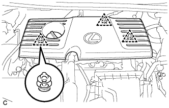
Установите крышку, закрепив ее 3 фиксаторами.
Note
-
Проверьте надежность зацепления фиксаторов.
-
Во время зацепления фиксаторов на крышке не прикладывайте чрезмерных усилий и не допускайте ударов. Это может привести к поломке крышки.
-
-
-
INSTALL RADIATOR SUPPORT OPENING COVER
-
Установите крышку отверстия кронштейна радиатора и закрепите ее 9 фиксаторами (для модели с 9 фиксаторами).
-
Установите крышку отверстия кронштейна радиатора и закрепите ее 7 фиксаторами (для модели с 7 фиксаторами).
-