ТОПЛИВНАЯ ФОРСУНКА СНЯТИЕ
-
PRECAUTION
Note
After turning the power switch off, waiting time may be required before disconnecting the cable from the negative (-) auxiliary battery terminal. Therefore, make sure to read the disconnecting the cable from the negative (-) auxiliary battery terminal notice before proceeding with work Click here.
-
DISCHARGE FUEL SYSTEM PRESSURE
-
REMOVE REAR NO. 2 FLOOR BOARD
-
Снимите панель заднего пола № 2.
-
-
REMOVE REAR DECK FLOOR BOX
-
Снимите заднюю напольную коробку полки багажного отделения.
-
-
REMOVE REAR NO. 3 FLOOR BOARD
-
Снимите панель заднего пола № 3.
-
-
REMOVE DECK FLOOR BOX RH
-
Снимите фиксатор.
-
Освободите 6 направляющих и снимите правую напольную коробку полки багажного отделения.
-
-
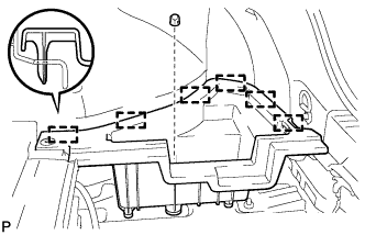
REMOVE REAR FLOOR BOARD UPPER NO. 3 PLATE
-
Освободите 4 захвата и 2 направляющих, и снимите верхнюю пластину панели заднего пола № 3.
-
-
DISCONNECT CABLE FROM NEGATIVE AUXILIARY BATTERY TERMINAL
Note
When disconnecting the cable, some systems need to be initialized after the cable is reconnected Click here.
-
REMOVE RADIATOR SUPPORT OPENING COVER
-
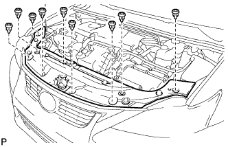
Освободите 9 фиксаторов и снимите крышку кронштейна радиатора (для модели с 9 фиксаторами).
-
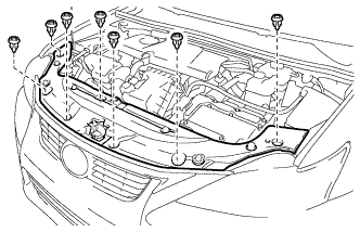
Освободите 7 фиксаторов и снимите крышку кронштейна радиатора (для модели с 7 фиксаторами).
-
-
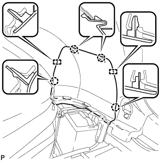
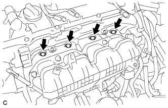
REMOVE NO. 2 CYLINDER HEAD COVER
-
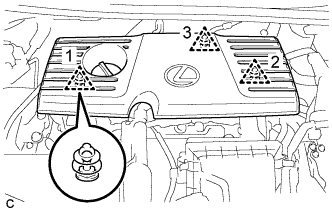
Снимите 3 фиксатора и крышку головки блока цилиндров № 2.
Note
-
Отсоедините фиксаторы в порядке, показанном на рисунке.
-
Освобождая фиксатор 3, удерживайте край крышки за фиксатором 3 и приподнимайте крышку вертикально вверх.
-
Попытка освободить задний и передние фиксаторы за один прием может привести к поломке крышки.
-
Вытяните крышку прямо вверх, чтобы снять ее. При попытке вытягивать крышку вперед или тянуть ее вверх, удерживая за левый и правый края, крышка может сломаться.
-
-
-
REMOVE AIR CLEANER CAP SUB-ASSEMBLY
-
Отсоедините разъем и зажим жгута проводов.
-
Отсоедините шланг охлаждающей жидкости от зажима.
-
Освободите 2 зажима и снимите крышку воздушного фильтра в сборе.
-
Ослабьте хомут шланга и отсоедините шланг воздушного фильтра.
-
-
REMOVE INLET AIR CLEANER ASSEMBLY
-
Отсоедините шланг охлаждающей жидкости от зажима шланга.
-
Отсоедините зажим жгута проводов от входного патрубка воздушного фильтра в сборе.
-
Выверните 2 болта и снимите 2 фиксатора и входной патрубок воздушного фильтра.
-
-
REMOVE AIR CLEANER CASE
-
Извлеките фильтрующий элемент воздушного фильтра в сборе из корпуса воздушного фильтра.
-
Отсоедините шланг охлаждающей жидкости от зажима.
-
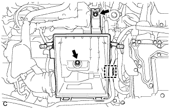
Выверните 2 болта и снимите корпус воздушного фильтра.
-
-
REMOVE AIR CLEANER HOSE ASSEMBLY
-
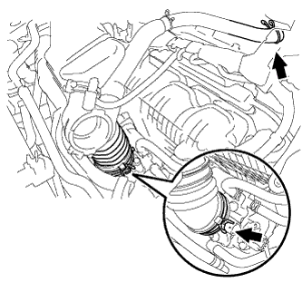
Отсоедините шланг вентиляции картера от крышки головки блока цилиндров.
-
Ослабьте зажим шланга и снимите шланг воздушного фильтра с корпуса дроссельной заслонки.
-
-
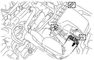
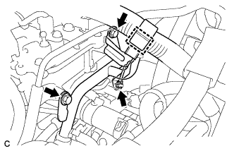
DISCONNECT ENGINE WIRE
-
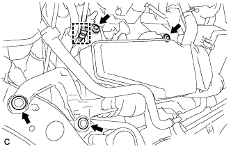
Disconnect the 4 fuel injector connectors.
-
Disconnect the 4 connectors.
-
Remove the bolt.
-
Disengage the 2 clamps to disconnect the wire harness.
-
-
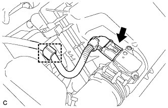
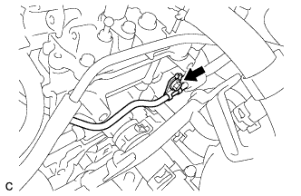
DISCONNECT FUEL TUBE SUB-ASSEMBLY
-
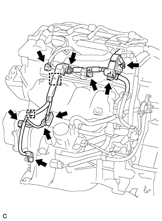
Release the claw and remove the No. 1 fuel pipe clamp.
-
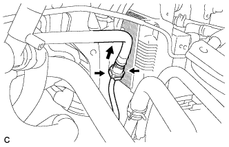
Pinch the retainer of the fuel tube connector, and then pull the fuel tube connector off of the fuel pipe.
Note
-
Check for foreign matter in the fuel pipe around the fuel tube connector. Clean it if necessary. Foreign matter can affect the ability of the O-ring to seal the fuel tube connector and fuel pipe.
-
Do not use any tools to separate the fuel tube connector and fuel pipe.
-
Do not forcefully bend, kink or twist the fuel tube.
-
Keep the fuel tube connector and fuel pipe free from foreign matter.
-
If the fuel tube connector and fuel pipe are stuck together, pinch the fuel tube connector and turn it carefully to disconnect it.
-
Put the fuel tube connector and fuel pipe in plastic bags to prevent damage and contamination.
-
-
-
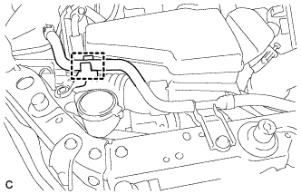
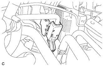
SEPARATE WATER BY-PASS PIPE
-
Disengage the clamp to disconnect the wire harness.
-
Remove the 2 bolts and nut, and separate the water by-pass pipe.
-
-
REMOVE FUEL DELIVERY PIPE SUB-ASSEMBLY
-
Remove the bolt.
-
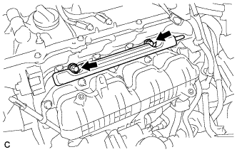
Remove the 2 bolts and fuel delivery pipe sub-assembly.
Note
Be careful not to drop the fuel injectors when removing the fuel delivery pipe.
-
-
REMOVE NO. 1 DELIVERY PIPE SPACER
-
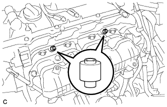
Remove the 2 delivery pipe spacers from the cylinder head.
-
-
REMOVE FUEL INJECTOR ASSEMBLY
-
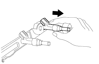
Pull the 4 fuel injector assemblies out of the fuel delivery pipe sub-assembly.
-
Remove the O-ring from each fuel injector assembly.
-
For reinstallation, attach a tag or label to each injector shaft.
Note
Prevent entry of foreign objects by covering the fuel injectors with plastic bags.
-
Remove the 4 injector vibration insulators.
-