БЛОК ДВИГАТЕЛЯ УСТАНОВКА
-
INSTALL IGNITION COIL ASSEMBLY
-
Установите 4 катушки зажигания и закрепите их 4 болтами.
- Torque:
- 10 Н*м { 102 кгс*см, 7 фунт-сила-футов }
Note
При установке катушек зажигания соблюдайте осторожность, чтобы не повредить наконечники свечей зажигания о края отверстия в крышке головки блока цилиндров или верхнюю кромку трубки свечного колодца.
-
Подсоедините разъемы 4 катушек зажигания.
-
-
INSTALL VENTILATION HOSE
-
Install the ventilation hose to the ventilation valve.
-
-
INSTALL EXHAUST MANIFOLD
-
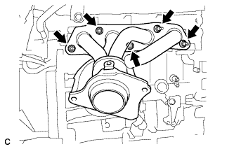
Install a new gasket and the exhaust manifold with the 5 nuts.
- Torque:
- 21 N*m { 214 kgf*cm, 15 ft.*lbf }
-
-
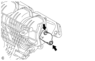
INSTALL MANIFOLD STAY
-
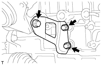
Install the manifold stay with the 3 bolts.
- Torque:
- 43 N*m { 438 kgf*cm, 32 ft.*lbf }
-
-
INSTALL NO. 1 EXHAUST MANIFOLD HEAT INSULATOR
-
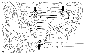
Install the No. 1 exhaust manifold heat insulator with the 3 bolts.
- Torque:
- 12 N*m { 122 kgf*cm, 9 ft.*lbf }
-
-
INSTALL FUEL INJECTOR ASSEMBLY
-
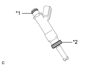
Text in Illustration *1 O-ring *2 Injector Vibration Insulator Install a new injector vibration insulator and O-ring to each fuel injector assembly.
-
Apply a light coat of gasoline or spindle oil to the contact surfaces of the new O-ring on each fuel injector assembly.
-
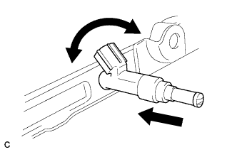
While turning the fuel injector assembly left and right, install it onto the fuel delivery pipe sub-assembly.
Note
-
Do not damage the fuel injector assembly or O-ring.
-
Do not twist the O-ring.
-
After installing each fuel injector, check that it turns smoothly. If not, replace the O-ring with a new one.
-
-
-
INSTALL NO. 1 DELIVERY PIPE SPACER
-
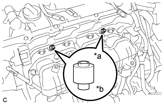
Text in Illustration *a Delivery Pipe Side *b Cylinder Head Side Install the 2 No. 1 delivery pipe spacers onto the cylinder head.
Note
Install the No. 1 delivery pipe spacers in the correct direction.
-
-
INSTALL FUEL DELIVERY PIPE SUB-ASSEMBLY
-
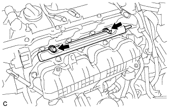
Install the fuel delivery pipe sub-assembly with the 4 fuel injector assemblies and install the 2 bolts.
- Torque:
- 21 N*m { 214 kgf*cm, 15 ft.*lbf }
Note
-
Do not drop the fuel injectors when installing the fuel delivery pipe sub-assembly.
-
Check that the fuel injector assemblies rotate smoothly after installing the fuel delivery pipe sub-assembly.
-
Install the bolt to secure the fuel delivery pipe sub-assembly.
- Torque:
- 21 N*m { 214 kgf*cm, 15 ft.*lbf }
-
-
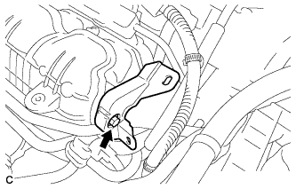
INSTALL FUEL VAPOR FEED PIPE
-
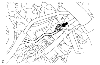
Install the fuel vapor feed pipe with the bolt.
- Torque:
- 21 N*m { 214 kgf*cm, 15 ft.*lbf }
-
-
INSTALL INTAKE MANIFOLD
-
Install a new No. 1 intake manifold to head gasket to the intake manifold.
-
Install the intake manifold with the 2 bolts and 2 nuts.
- Torque:
- 28 N*m { 286 kgf*cm, 21 ft.*lbf }
-
Connect the fuel vapor feed hose and ventilation hose.
-
Install a new O-ring to the engine oil level dipstick guide sub-assembly.
-
Apply a light coat of engine oil to the O-ring.
-
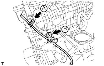
Install the engine oil level dipstick guide sub-assembly with the 2 bolts and connect the wire harness clamp.
- Torque:
- Bolt (A)
- 28 N*m { 286 kgf*cm, 21 ft.*lbf }
- Bolt (B)
- 21 N*m { 214 kgf*cm, 15 ft.*lbf }
-
Install the engine oil level dipstick.
-
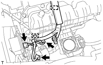
Connect the 2 wire harness clamps and 3 connectors.
-
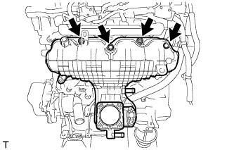
Install a new gasket and the surge tank cover with the 2 bolts.
- Torque:
- 10 N*m { 102 kgf*cm, 7 ft.*lbf }
-
Install the wire harness support with the bolt.
- Torque:
- 10 N*m { 102 kgf*cm, 7 ft.*lbf }
-
Connect the 2 wire harness clamps.
-
-
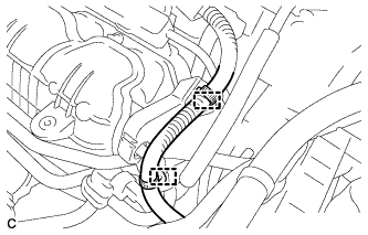
INSTALL WATER BY-PASS PIPE
-
Install the water by-pass pipe with the 2 bolts and nut.
- Torque:
- 21 N*m { 214 kgf*cm, 15 ft.*lbf }
-
Connect the 2 water hoses.
-
-
INSTALL ENGINE OIL LEVEL DIPSTICK GUIDE
-
Apply a light coat of engine oil to a new O-ring.
-
Install the O-ring to the engine oil level dipstick guide.
-
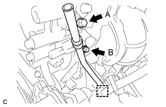
Install the engine oil level dipstick guide with the 2 bolts.
- Torque:
- Bolt A
- 28 N*m { 286 kgf*cm, 21 ft.*lbf }
- Bolt B
- 21 N*m { 214 kgf*cm, 15 ft.*lbf }
-
Connect the clamp to the engine oil level dipstick guide.
-
Install the oil dipstick.
-
-
INSTALL THROTTLE BODY ASSEMBLY
-
Установите на впускной коллектор новую прокладку.
-
Установите корпус дроссельной заслонки в сборе и закрепите 2 болтами и 2 гайками.
- Torque:
- 10 Н*м { 102 кгс*см, 7 фунт-сила-футов }
-
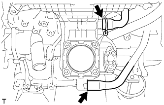
Подсоедините 2 перепускных шланга охлаждающей жидкости и разъем корпуса дроссельной заслонки.
-
-
INSTALL ENGINE HANGERS
-

Install the 2 engine hangers with the 2 bolts.
- Torque:
- 43 N*m { 438 kgf*cm, 32 ft.*lbf }
Part Name Part No. No. 1 engine hanger 12281-37021 No. 2 engine hanger 12282-37011 Bolt 91552-81050
-
-
REMOVE ENGINE STAND
-
Remove the engine from the engine stand.
-