РАСПРЕДВАЛ УСТАНОВКА

-
INSTALL NO. 1 CAMSHAFT BEARING
-
Clean both surfaces of the bearings.
-
Install the 2 No. 1 camshaft bearings.
-
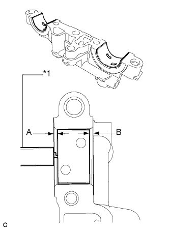
Text in Illustration *1 Vernier Caliper Using a vernier caliper, measure the distance between the bearing cap edge and the camshaft bearing edge.
Standard dimension (A - B) 0.7 mm (0.0276 in.) or less Note
Position the bearings to the center of the bearing cap by measuring dimensions A and B.
-
-
INSTALL NO. 2 CAMSHAFT BEARING
-
Clean both surfaces of the bearings.
-
Install the 2 No. 2 camshaft bearings.
-
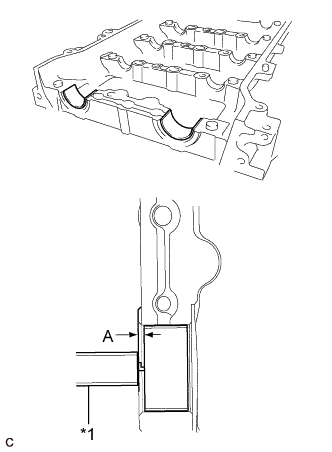
Text in Illustration *1 Vernier Caliper Using a vernier caliper, measure the distance between the bearing cap edge and the camshaft bearing edge.
Standard dimension (A) 1.05 to 1.75 mm (0.0413 to 0.0689 in.) Note
Position the bearings to the center of the bearing cap by measuring dimension A.
-
-
INSTALL NO. 2 CAMSHAFT
-
Clean the camshaft journals.
-
Apply a light coat of engine oil to the camshaft journals, camshaft housings and bearing caps.
-
Install the No. 2 camshaft to the camshaft housing.
-
-
INSTALL CAMSHAFT
-
Clean the camshaft journals.
-
Apply a light coat of engine oil to the camshaft journals, camshaft housings and bearing caps.
-
Install the camshaft to the camshaft housing.
-
-
INSTALL BEARING CAP
-
Apply engine oil to the camshaft journals, camshaft housings and bearing caps.
-

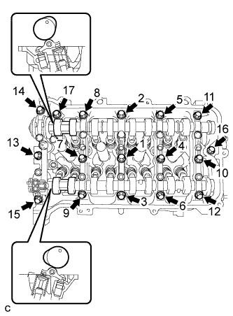
Text in Illustration *1 Knock Pin *2 Camshaft Make sure of the marks and numbers on the camshaft bearing caps and place them in each proper position and direction.
-
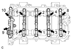
Tighten the 10 bolts in the order shown in the illustration.
- Torque:
- 16 N*m { 163 kgf*cm, 12 ft.*lbf }
-
-
INSTALL CAMSHAFT HOUSING SUB-ASSEMBLY
-
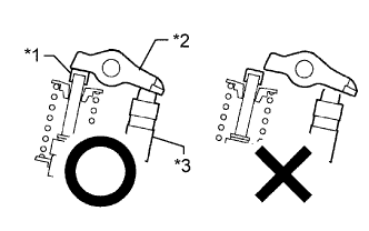
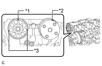
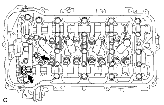
Text in Illustration *1 Valve Stem Cap *2 Valve Rocker Arm *3 Valve Lash Adjuster Check that the valve rocker arms are installed as shown in the illustration.
-
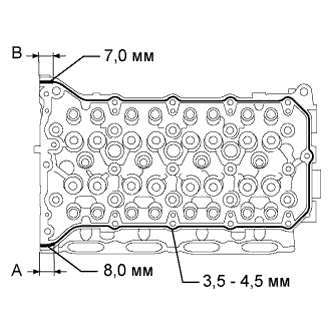
Apply seal packing in a continuous line as shown in the illustration.
Seal packing Toyota Genuine Seal Packing Black, Three Bond 1207B or equivalent Standard Seal Diameter Area Specified Condition Continuous line 3.5 to 4.5 mm (0.138 to 0.177 in.) A 8.0 mm (0.315 in.) B 7.0 mm (0.276 in.) Application Length A and B 15 mm (0.591 in.) Note
-
Remove any oil from the contact surfaces.
-
Install the camshaft housing within 3 minutes and tighten the bolts within 10 minutes of applying seal packing.
-
Do not start the engine for at least 2 hours after installation.
-
-
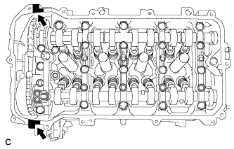
Set the camshaft and No. 2 camshaft as shown in the illustration.
-
Install the camshaft housing with the 17 bolts and tighten them in the order shown in the illustration.
- Torque:
- 27 N*m { 275 kgf*cm, 20 ft.*lbf }
Note
-
After installing the camshaft housing, make sure that the cam lobes are positioned as shown in the illustration.
-
If any of the bolts is loosened during installation, remove the camshaft housing, clean the installation surfaces, and reapply seal packing.
-
If the camshaft housing is removed because any of the bolts is loosened during installation, make sure that the previously applied seal packing does not enter any oil passages.
-
After installing the camshaft housing, wipe off any seal packing that seeped out from between the housing and cylinder head.
-
-
INSTALL CAMSHAFT TIMING SPROCKET
-
Tighten the flange bolt with the camshaft timing sprocket secured in place.
- Torque:
- 54 N*m { 551 kgf*cm, 40 ft.*lbf }
-
-
INSTALL CAMSHAFT TIMING GEAR ASSEMBLY
-
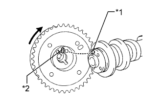
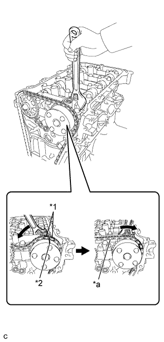
Text in Illustration *1 Straight Pin *2 Key Groove Put the camshaft timing gear and camshaft together with the straight pin and key groove misaligned as shown in the illustration.
Note
Do not forcefully push in the camshaft timing gear. This may cause the camshaft straight pin tip to damage the installation surface of the camshaft timing gear.
-
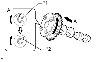
Text in Illustration *1 Straight Pin *2 Key Groove Turn the camshaft timing gear as shown in the illustration while pushing it gently against the camshaft. Push further at the position where the pin fits into the groove.
Note
Do not turn the camshaft timing gear in the retard direction (clockwise).
-
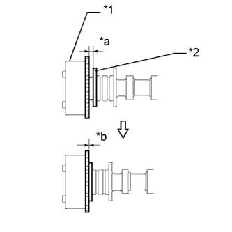
Text in Illustration *1 Camshaft Timing Gear *2 Flange *a Clearance *b No Clearance Check that there is no clearance between the camshaft timing gear and camshaft flange.
-
Tighten the flange bolt with the camshaft timing gear secured in place.
- Torque:
- 54 N*m { 551 kgf*cm, 40 ft.*lbf }
-
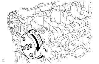
Text in Illustration *a Lock Check that the camshaft timing gear can move in the retard direction (clockwise) and lock it in the most retarded position.
-
-
INSTALL NO. 1 CHAIN VIBRATION DAMPER
-
Install the chain vibration damper with the 2 bolts.
- Torque:
- 21 N*m { 214 kgf*cm, 15 ft.*lbf }
-
-
SET NO. 1 CYLINDER TO TDC/COMPRESSION
-
Text in Illustration *1 Timing Gear Key Temporarily install the crankshaft pulley bolt.
-
Turn the crankshaft to position the timing gear key to the top.
-
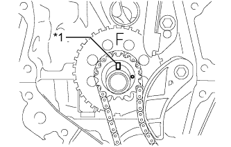
Text in Illustration *1 Timing Mark (Rectangle) *2 Timing Mark *3 Mark (Circle) Check that the timing marks on the camshaft timing gear and camshaft timing sprocket are aligned as shown in the illustration.
Tech Tips
There are 3 marks on the camshaft timing sprocket. Make sure that the timing mark (rectangle) is at the top.
-
Remove the crankshaft pulley bolt.
-
-
INSTALL CHAIN SUB-ASSEMBLY
-
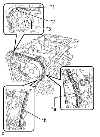
Text in Illustration *1 Mark Plate (Orange) *2 Timing Mark (Rectangle) *3 Mark (Circle) *a Place the Chain on the Sprocket *b Pass the Chain through the Damper Align the mark plate (orange) with the timing mark as shown in the illustration and install the chain.
Tech Tips
-
There are 3 marks on the camshaft timing sprocket. Make sure to align the mark plate with the timing mark (rectangle).
-
Be sure to position the mark plate at the front of the engine.
-
The mark plate on the camshaft side is colored orange.
-
Do not pass the chain around the sprocket of the camshaft timing gear. Only place it on the sprocket.
-
Pass the chain through the No. 1 vibration damper.
-
-
Place the chain on the crankshaft without passing it around the shaft.
-
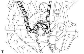
Text in Illustration *1 Mark Plate (Orange) *2 Timing Mark *a Tension the Chain Hold the hexagonal portion of the camshaft with a wrench and turn the camshaft timing gear counterclockwise to align the mark plate (orange) and timing mark, and then install the chain.
-
Hold the hexagonal portion of the camshaft with a wrench and turn the camshaft timing gear clockwise.
Tech Tips
To tension the chain, slowly turn the camshaft timing gear clockwise to prevent the chain from being misaligned.
-
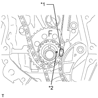
Text in Illustration *1 Mark Plate (Yellow or Pink) *2 Timing Mark Align the mark plate (yellow or pink) and timing mark and install the chain to the crankshaft timing gear.
Tech Tips
The mark plate on the crankshaft side is colored pink.
-
-
CHECK NO. 1 CYLINDER TO TDC/COMPRESSION
-
Check each timing mark at TDC/compression.
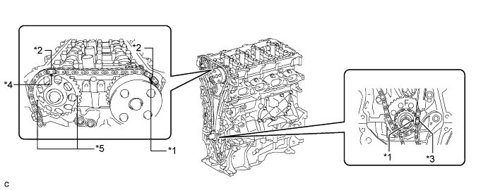
Text in Illustration *1 Timing Mark *2 Mark Plate (Orange) *3 Mark Plate (Yellow or Pink) *4 Timing Mark (Rectangle) *5 Mark (Circle) - - Tech Tips
There are 3 marks on the camshaft timing sprocket. Make sure that the timing mark (rectangle) is at the top.
-
-
INSTALL NO. 2 CHAIN VIBRATION DAMPER
-
Install the No. 2 chain vibration damper with the 2 bolts.
- Torque:
- 10 N*m { 102 kgf*cm, 7 ft.*lbf }
-
-
INSTALL CHAIN TENSIONER SLIPPER
-
Install the chain tensioner slipper to the cylinder block.
-
-
INSTALL TIMING CHAIN COVER OIL SEAL
-
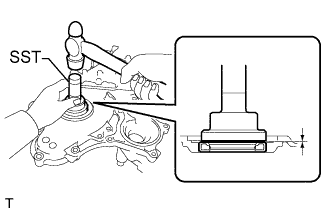
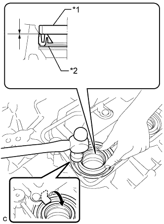
Using SST and a hammer, tap in a new oil seal until its surface is flush with the timing chain cover edge.
- SST
- 09223-22010
Note
-
Keep the lip free from foreign matter.
-
Do not tap on the oil seal at an angle.
-
Make sure that the oil seal edge does not stick out of the timing chain case.
Tech Tips
Tap in the oil seal so that it is positioned within 1.0 mm (0.0394 in.) from the edge of the timing chain case.
-
Apply MP grease to the lip of the oil seal.
-
-
INSTALL TIMING CHAIN COVER SUB-ASSEMBLY
-
Remove any old packing (FIPG) material and be careful not to drop any oil on the contact surfaces of the timing chain cover, cylinder head and cylinder block.
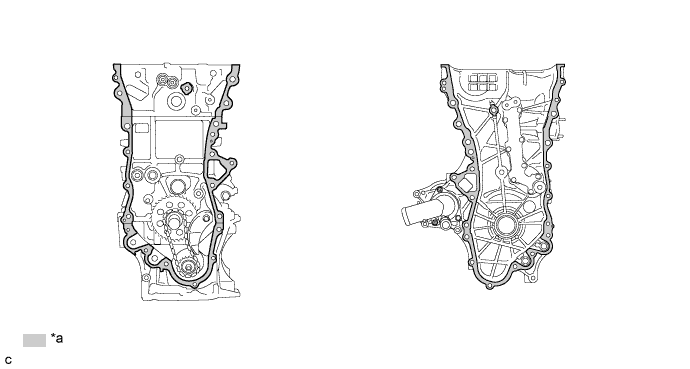
Text in Illustration *a Clean and degrease - - -
Install 3 new O-rings.
-
Apply seal packing as shown in the illustration.
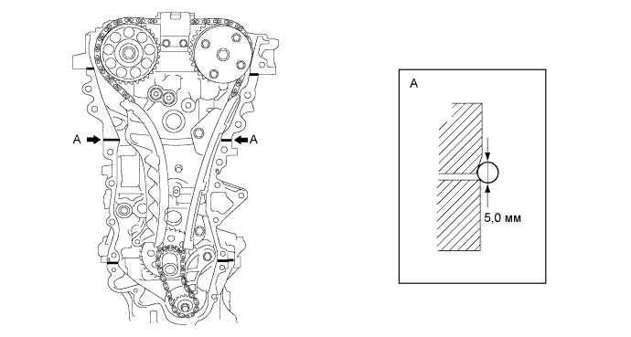
Seal packing Toyota Genuine Seal Packing Black, Three Bond 1207B or equivalent Seal diameter 5.0 mm (0.197 in.) Note
-
Remove any oil from the contact surfaces.
-
Install the chain cover within 3 minutes of applying seal packing.
-
Do not start the engine for at least 2 hours after installing the timing chain cover sub-assembly.
-
-
Apply seal packing to the timing chain cover in a line as shown in the following illustration.
Note
-
When the contact surfaces are wet, wipe them with an oil-free cloth before applying seal packing.
-
Install the chain cover within 3 minutes and tighten the bolts within 15 minutes of applying seal packing.
-
Do not start the engine for at least 2 hours after installation.
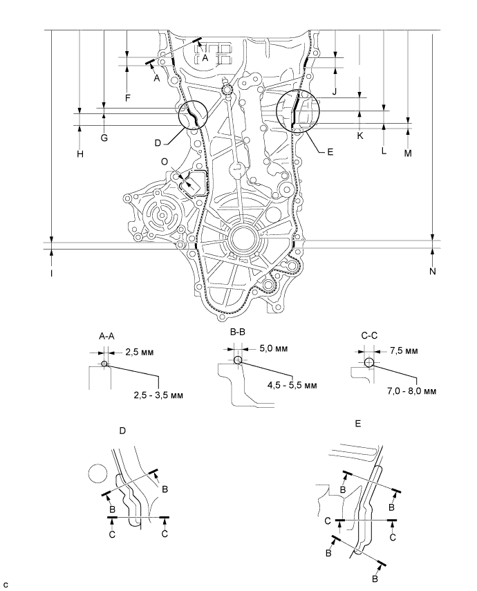
Seal Packing Item Seal Packing Dashed line Toyota Genuine Seal Packing Black, Three Bond 1207B or equivalent Continuous line Alternate long and short dashed line Toyota Genuine Seal Packing 1282B, Three Bond 1282B or equivalent Application Specification Area Seal Packing Diameter Distance from Edge of Cover to: Seal Packing Application Length Distance from Top of Cover to Top of Seal Packing Dashed line 2.5 to 3.0 mm (0.0984 to 0.118 in.) Center of seal packing
2.5 mm (0.0984 in.)
- - Continuous line 4.5 to 5.5 mm (0.177 to 0.217 in.) or 7.0 to 8.0 mm (0.276 to 0.315 in.) - - - Alternate long and short dashed line 4.0 mm (0.157 in.) Center of seal packing
3.0 mm (0.118 in.)
- - A - A 2.5 to 3.5 mm (0.0984 to 0.138 in.) Center of seal packing
2.5 mm (0.0984 in.)
- - B - B 4.5 to 5.5 mm (0.177 to 0.217 in.) Opposite edge of seal packing
5.0 mm (0.197 in.)
- - C - C 7.0 to 8.0 mm (0.276 to 0.315 in.) Opposite edge of seal packing
7.5 mm (0.295 in.)
- - F 4.5 to 5.5 mm (0.177 to 0.217 in.) - 15.5 mm (0.610 in.) 50.4 mm (1.98 in.) G 4.5 to 5.5 mm (0.177 to 0.217 in.) - 10.3 mm (0.406 in.) 143.1 mm (5.63 in.) H 7.0 to 8.0 mm (0.276 to 0.315 in.) - 19.5 mm (0.768 in.) 153.4 mm (6.04 in.) I 4.5 to 5.5 mm (0.177 to 0.217 in.) - 16.0 mm (0.630 in.) 385.8 mm (1.27 ft.) J 4.5 to 5.5 mm (0.177 to 0.217 in.) - 18.6 mm (0.732 in.) 51.4 mm (2.02 in.) K 4.5 to 5.5 mm (0.177 to 0.217 in.) - 25.3 mm (0.996 in.) 121.9 mm (4.80 in.) L 7.0 to 8.0 mm (0.276 to 0.315 in.) - 25.8 mm (1.02 in.) 147.2 mm (5.80 in.) M 4.5 to 5.5 mm (0.177 to 0.217 in.) - 5.1 mm (0.201 in.) 173.0 mm (6.81 in.) N 4.5 to 5.5 mm (0.177 to 0.217 in.) - 14.6 mm (0.575 in.) 385.8 mm (1.27 ft.) O 4.0 mm (0.157 in.) Center of seal packing
3.0 mm (0.118 in.)
- - Note
-
When the contact surfaces are wet, wipe them with an oil-free cloth before applying seal packing.
-
Install the timing chain cover within 3 minutes and tighten the bolts within 10 minutes of applying seal packing.
-
After applying seal packing to the timing chain cover, install the engine mounting bracket and oil filter bracket within 10 minutes.
-
Do not add engine oil for at least 2 hours after installation.
-
-
Clean the bolt and fitting hole.
-
Install the timing chain cover.
-
Temporarily tighten the engine mounting bracket RH with the 3 bolts.
Note
-
Install the mounting bracket within 10 minutes of installing the chain cover.
-
Do not start the engine for at least 2 hours after installation.
Bolt Length Item Length Bolt 80 mm (3.15 in.) -
-
Install 2 new O-rings.
-
Temporarily tighten the oil filter bracket with the 4 bolts.
Note
-
Install the oil filter bracket within 10 minutes of installing the chain cover.
-
Do not start the engine for at least 2 hours after installation.
Bolt Length Item Length Bolt 35 mm (1.38 in.) -
-
Install the timing chain cover with the 25 bolts and seal washer as shown in the illustration.
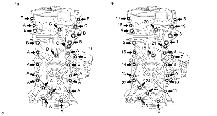
Text in Illustration *1 Seal Washer - - *a Torque *b Bolt Torque Order - Torque:
- Bolt A, E, F
- 26 N*m { 260 kgf*cm, 19 ft.*lbf }
- Bolt B, C
- 51 N*m { 520 kgf*cm, 38 ft.*lbf }
- Bolt D
- 10 N*m { 102 kgf*cm, 7 ft.*lbf }
Note
-
Apply adhesive 1324 to the threads of the bolt F.
-
When the contact surfaces are wet, wipe them with an oil-free cloth before applying seal packing.
-
Install the chain cover within 3 minutes and tighten the bolts within 15 minutes of applying the seal packing.
-
Do not add engine oil for at least 2 hours after installing the chain cover.
-
Do not start the engine for at least 2 hours after installing the chain cover.
Bolt Length Item Length Bolt A, F 35 mm (1.38 in.) Bolt B 55 mm (2.16 in.) Bolt C 80 mm (3.15 in.) Bolt D 40 mm (1.57 in.) Bolt E 55 mm (2.16 in.)
-
-
INSTALL CRANKSHAFT PULLEY
-
Совместите шпонку шкива со шпоночной канавкой шкива.
-
Установите шкив коленчатого вала на коленчатый вал.
-
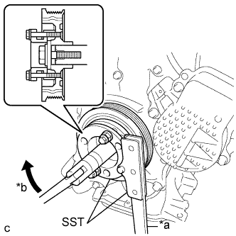
Обозначения на рисунке *a Удерживайте *b Поверните С помощью SST зафиксируйте шкив на месте и затяните болт.
- SST
- 09213-58014 ( 91551-80840 )
- 09330-00021
- Torque:
- 190 Н*м { 1937 кгс*см, 140 фунт-сила-футов }
-
-
INSTALL NO. 1 CHAIN TENSIONER ASSEMBLY
-
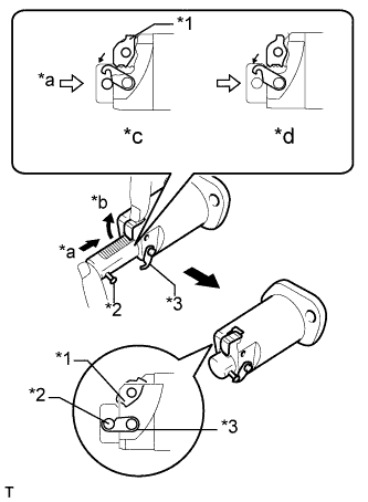
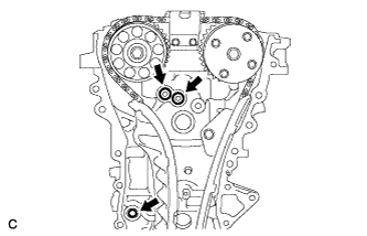
Text in Illustration *1 Cam *2 Pin *3 Hook *a Push *b Raise *c CORRECT *d INCORRECT Release the cam, and then fully push in the plunger and engage the hook to the pin so that the plunger is in the position shown in the illustration.
Note
Make sure that the cam engages the first tooth of the plunger to allow the hook to pass over the pin.
-
Install a new gasket, the bracket and chain tensioner with the 2 nuts.
- Torque:
- 12 N*m { 122 kgf*cm, 9 ft.*lbf }
Note
If the hook releases the plunger while the chain tensioner is being installed, set the hook again.
-
Text in Illustration *1 Pin *2 Hook *a Push *b Turn *c Disconnect Rotate the crankshaft counterclockwise slightly and check that the hook is released.
-
Text in Illustration *1 Plunger *a Turn *b Plunger Extended Turn the crankshaft clockwise and check that the plunger is extended.
-
-
INSTALL SPARK PLUG TUBE GASKET
-
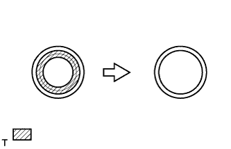
Резцом срежьте уплотнительную часть снятой прокладки.
Обозначения на рисунке 
Срезная часть -
Обозначения на рисунке *1 Прокладка трубки свечного колодца без уплотнения *2 Новая прокладка трубки свечного колодца С помощью молотка и прокладки трубки свечного колодца со срезанным уплотнением равномерно запрессуйте новую прокладку трубки свечного колодца.
Note
-
Не допускайте попадания на кромку посторонних частиц.
-
Не следует запрессовывать прокладку трубки свечного колодца.
Tech Tips
Если прокладка трубки свечного колодца, которая используется для установки новой прокладки, деформирована и ее не удается поместить на новую прокладку, устраните деформацию плоскогубцами.
-
-
Установите захваты отражающей вентиляционной заслонки в исходные положения.
-
-
INSTALL CYLINDER HEAD COVER GASKET
-
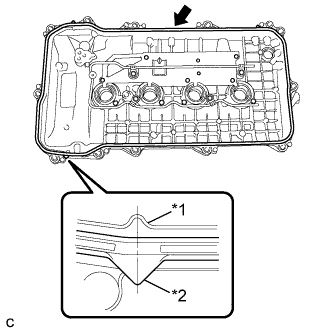
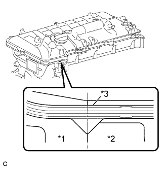
Обозначения на рисунке *1 Крышка головки блока цилиндров *2 Прокладка крышки головки блока цилиндров Установите новую прокладку крышки головки блока цилиндров.
Note
-
Удалите все масло с контактной поверхности.
-
Отклонение центра ребра крышки головки блока цилиндров от центра выступа прокладки головки блока цилиндров должно находиться в пределах 4,0 мм (0,157 дюйма).
-
-
-
INSTALL CYLINDER HEAD COVER SUB-ASSEMBLY
-
Установите 2 новых прокладки на крышки подшипников распредвала.
-
Нанесите герметик, как показано на рисунке.
Герметик Фирменный герметик Seal Packing Black от компании Toyota, Three bond 1207B или аналогичный Номинальный диаметр 4,0 мм (0,157 дюйма) Note
-
Удалите все масло с контактной поверхности.
-
После нанесения герметика в течение 3 мин установите крышку головки блока цилиндров в сборе и в течение 15 мин затяните болты.
-
Не запускайте двигатель в течение 2 часов после установки.
-
-
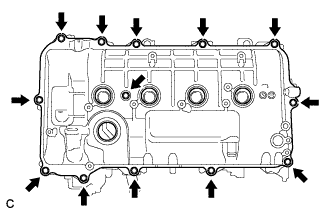
Обозначения на рисунке *1 Крышка цепного привода газораспределительного механизма *2 Кожух распредвала *3 Прокладка крышки головки блока цилиндров Установите крышку головки блока цилиндров с новой уплотнительной прокладкой и закрепите 13 болтами.
- Torque:
- 10 Н*м { 102 кгс*см, 7 фунт-сила-футов }
Note
Отклонение контактных поверхностей крышки цепного привода газораспределительного механизма и кожуха распредвала от центра выступа прокладки головки блока цилиндров должно находиться в пределах 4,0 мм (0,157 дюйма).
-
-
INSTALL IGNITION COIL ASSEMBLY
-
Установите 4 катушки зажигания и закрепите их 4 болтами.
- Torque:
- 10 Н*м { 102 кгс*см, 7 фунт-сила-футов }
Note
При установке катушек зажигания соблюдайте осторожность, чтобы не повредить наконечники свечей зажигания о края отверстия в крышке головки блока цилиндров или верхнюю кромку трубки свечного колодца.
-
Подсоедините разъемы 4 катушек зажигания.
-
-
INSTALL FUEL INJECTOR ASSEMBLY
-
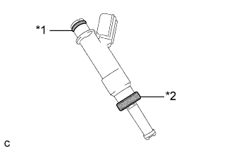
Text in Illustration *1 O-ring *2 Injector Vibration Insulator Install a new injector vibration insulator and O-ring to each fuel injector assembly.
-
Apply a light coat of gasoline or spindle oil to the contact surfaces of the new O-ring on each fuel injector assembly.
-
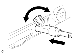
While turning the fuel injector assembly left and right, install it onto the fuel delivery pipe sub-assembly.
Note
-
Do not damage the fuel injector assembly or O-ring.
-
Do not twist the O-ring.
-
After installing each fuel injector, check that it turns smoothly. If not, replace the O-ring with a new one.
-
-
-
INSTALL NO. 1 DELIVERY PIPE SPACER
-
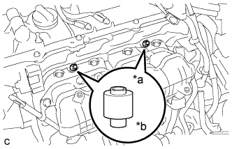
Text in Illustration *a Delivery Pipe Side *b Cylinder Head Side Install the 2 No. 1 delivery pipe spacers onto the cylinder head.
Note
Install the No. 1 delivery pipe spacers in the correct direction.
-
-
INSTALL FUEL DELIVERY PIPE SUB-ASSEMBLY
-
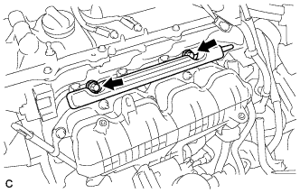
Install the fuel delivery pipe sub-assembly with the 4 fuel injector assemblies and install the 2 bolts.
- Torque:
- 21 N*m { 214 kgf*cm, 15 ft.*lbf }
Note
-
Do not drop the fuel injectors when installing the fuel delivery pipe sub-assembly.
-
Check that the fuel injector assemblies rotate smoothly after installing the fuel delivery pipe sub-assembly.
-
Install the bolt to secure the fuel delivery pipe sub-assembly.
- Torque:
- 21 N*m { 214 kgf*cm, 15 ft.*lbf }
-
-
INSTALL FUEL VAPOR FEED PIPE
-
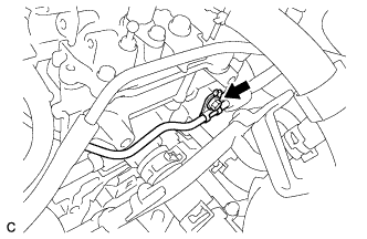
Install the fuel vapor feed pipe with the bolt.
- Torque:
- 21 N*m { 214 kgf*cm, 15 ft.*lbf }
-
-
INSTALL INTAKE MANIFOLD
-
При наличии шпильки:
-
С помощью торцевого ключа "TORX" E6 вверните во впускной коллектор 2 резьбовые шпильки.
- Torque:
- 5,0 Н*м { 51 кгс*см, 44 фунт-сила-дюйма }
Tech Tips
Если шпилька деформирована или повреждена резьба, замените шпильку.
-
-
Установите новую прокладку между впускным коллектором № 1 и головкой.
-
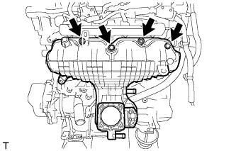
Установите впускной коллектор и закрепите его 2 болтами и 2 гайками.
- Torque:
- 28 Н*м { 286 кгс*см, 21 фунт-сила-фут }
-
Подсоедините питающий шланг паров топлива и шланг вентиляции картера.
-
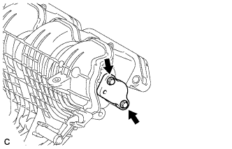
Установите новое кольцевое уплотнение на трубку щупа проверки уровня моторного масла в сборе.
-
Нанесите на уплотнительное кольцо тонкий слой моторного масла.
-
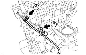
Закрепите трубку щупа проверки уровня моторного масла в сборе 2 болтами и подсоедините зажим жгута проводов.
- Torque:
- Болт (A)
- 28 Н*м { 286 кгс*см, 21 фунт-сила-фут }
- Болт (B)
- 21 Н*м { 214 кгс*см, 15 фунт-сила-футов }
-
Установите щуп проверки уровня моторного масла.
-
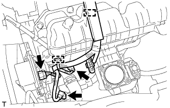
Подсоедините 2 зажима жгута проводов и 3 разъема.
-
Закрепите новую прокладку и крышку расширительного бачка 2 болтами.
- Torque:
- 10 Н*м { 102 кгс*см, 7 фунт-сила-футов }
-
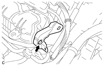
Закрепите опору жгута проводов болтом.
- Torque:
- 10 Н*м { 102 кгс*см, 7 фунт-сила-футов }
-
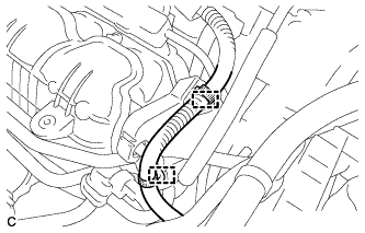
Подсоедините 2 зажима жгутов проводов.
-
-
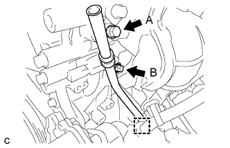
INSTALL WATER BY-PASS PIPE
-
Install the water by-pass pipe with the 2 bolts and nut.
- Torque:
- 21 N*m { 214 kgf*cm, 15 ft.*lbf }
-
Connect the 2 water hoses.
-
-
INSTALL ENGINE OIL LEVEL DIPSTICK GUIDE
-
Apply a light coat of engine oil to a new O-ring.
-
Install the O-ring to the engine oil level dipstick guide.
-
Install the engine oil level dipstick guide with the 2 bolts.
- Torque:
- Bolt A
- 28 N*m { 286 kgf*cm, 21 ft.*lbf }
- Bolt B
- 21 N*m { 214 kgf*cm, 15 ft.*lbf }
-
Connect the clamp to the engine oil level dipstick guide.
-
Install the oil dipstick.
-
-
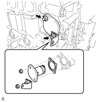
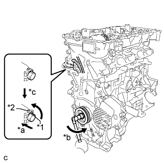
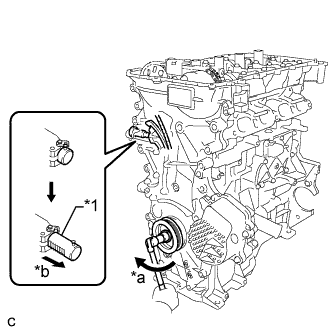
INSTALL THROTTLE BODY ASSEMBLY
-
Тип A:
-
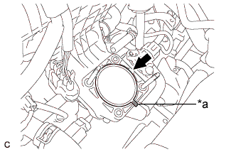
Установите на впускной коллектор новую прокладку.
Tech Tips
Расположите выступ прокладки, как показано на рисунке.
Обозначения на рисунке *1 Выступ -
Установите корпус дроссельной заслонки в сборе и закрепите 2 болтами и 2 гайками.
- Torque:
- 10 Н*м { 102 кгс*см, 7 фунт-сила-футов }
-
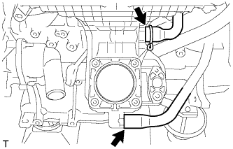
Подсоедините перепускные шланги охлаждающей жидкости № 1 и № 2.
-
Подсоедините разъем.
-
-
Тип B:
-
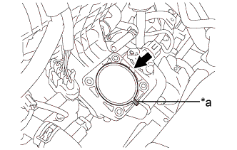
Установите на впускной коллектор новую прокладку.
Tech Tips
Расположите выступ прокладки, как показано на рисунке.
Обозначения на рисунке *1 Выступ -
Установите корпус дроссельной заслонки в сборе и закрепите 2 болтами и 2 гайками.
- Torque:
- 10 Н*м { 102 кгс*см, 7 фунт-сила-футов }
-
Подсоедините перепускные шланги охлаждающей жидкости № 1 и № 2.
-
Подсоедините разъем.
-
-
-
INSTALL ENGINE HANGERS
-

Install the 2 engine hangers with the 2 bolts.
- Torque:
- 43 N*m { 438 kgf*cm, 32 ft.*lbf }
Part Name Part No. No. 1 engine hanger 12281-37021 No. 2 engine hanger 12282-37011 Bolt 91552-81050
-
-
REMOVE ENGINE STAND
-
Remove the engine from the engine stand.
-
-
INSTALL ENGINE ASSEMBLY WITH TRANSAXLE