POWER WINDOW CONTROL SYSTEM Rear Power Window LH does not Operate with Rear Power Window Switch LH
DESCRIPTION
If the rear LH side manual UP / DOWN function does not operate, a malfunction may exist in the power window regulator motor assembly LH, rear power window regulator switch assembly, power window regulator master switch assembly or wire harness.
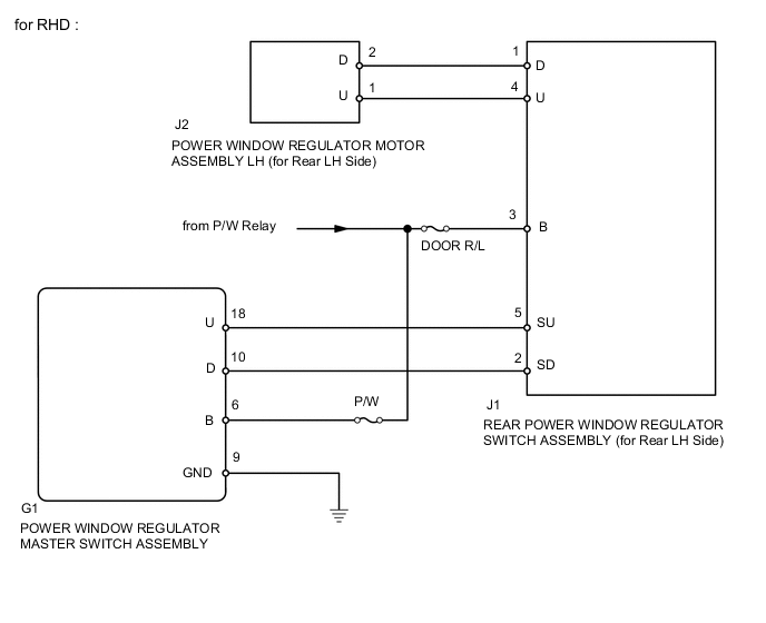
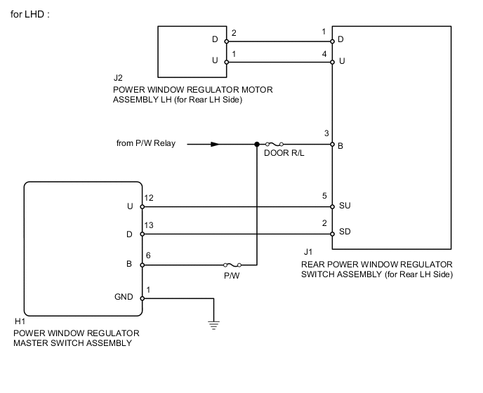
WIRING DIAGRAM
CAUTION / NOTICE / HINT
Note
Inspect the fuses for circuits related to this system before performing the following inspection procedure.
PROCEDURE
-
CHECK HARNESS AND CONNECTOR (POWER SOURCE)
-
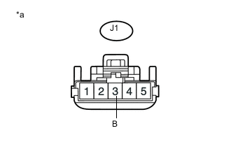
Text in Illustration *a Front view of wire harness connector
(Power Window Regulator Switch Assembly (for Rear LH Side))
Disconnect the J1 rear power window regulator switch assembly (for rear LH side) connector.
-
Measure the voltage according to the value(s) in the table below.
Standard voltage Tester Connection Condition Specified Condition J1-3 (B) - Body ground Ignition switch ON 11 to 14 V
NG 
REPAIR OR REPLACE HARNESS OR CONNECTOR
OK 
-
-
INSPECT REAR POWER WINDOW REGULATOR SWITCH ASSEMBLY (for Rear LH Side)
-
Remove the rear power window regulator switch assembly (for rear LH side) Click here.
-
Inspect the rear power window regulator switch assembly (for rear LH side) Click here.
NG
REPLACE REAR POWER WINDOW REGULATOR SWITCH ASSEMBLY (for Rear LH Side) Click here
OK
-
-
CHECK HARNESS AND CONNECTOR (POWER WINDOW REGULATOR SWITCH - POWER WINDOW MOTOR)
-
Disconnect the J1 rear power window regulator switch assembly (for rear LH side) connector.
-
Disconnect the J2 power window regulator motor assembly LH connector.
-
Measure the resistance according the value(s) in the table below.
Standard resistance (Check for Open) Tester Connection Condition Specified Condition J1-4 (U) - J2-1 (U) Always Below 1 Ω J1-1 (D) - J2-2 (D) Always Below 1 Ω Standard resistance (Check for Short) Tester Connection Condition Specified Condition J1-4 (U) - Body ground Always 10 kΩ or higher J1-1 (D) - Body ground Always 10 kΩ or higher
NG
REPAIR OR REPLACE HARNESS OR CONNECTOR
OK
-
-
INSPECT POWER WINDOW REGULATOR MOTOR ASSEMBLY LH (for Rear LH Side)
-
Remove the power window regulator motor assembly LH Click here.
-
Inspect the power window regulator motor assembly LH Click here.
NG
REPLACE POWER WINDOW REGULATOR MOTOR ASSEMBLY LH (for Rear LH Side) Click here
OK
-
-
CHECK HARNESS AND CONNECTOR (POWER WINDOW MASTER SWITCH - POWER WINDOW SWITCH)
-
Disconnect the G1*1 or H1*2 power window regulator master switch assembly connector.
-
Disconnect the J1 rear power window regulator switch assembly (for rear LH side) connector.
-
Measure the resistance according to the value(s) in the table below.
-
*1: for RHD
-
*2: for LHD
Standard resistance (Check for Open) for RHD Tester Connection Condition Specified Condition G1-18 (U) - J1-5 (SU) Always Below 1 Ω G1-10 (D) - J1-2 (SD) Always Below 1 Ω for LHD Tester Connection Condition Specified Condition H1-12 (U) - J1-5 (SU) Always Below 1 Ω H1-13 (D) - J1-2 (SD) Always Below 1 Ω Standard resistance (Check for Short) for RHD Tester Connection Condition Specified Condition G1-18 (U) - Body ground Always 10 kΩ or higher G1-10 (D) - Body ground Always 10 kΩ or higher for LHD Tester Connection Condition Specified Condition H1-12 (U) - Body ground Always 10 kΩ or higher H1-13 (D) - Body ground Always 10 kΩ or higher -
OK
REPLACE POWER WINDOW REGULATOR MASTER SWITCH ASSEMBLY Click here
NG
REPAIR OR REPLACE HARNESS OR CONNECTOR
-