AIR CONDITIONING PANEL(for Manual Air Conditioning System) INSPECTION
PROCEDURE
-
INSPECT NO. 1 HEATER CONTROL SUB-ASSEMBLY
-
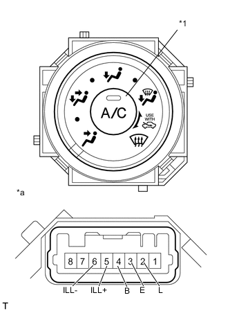
Text in Illustration *1 A/C Switch *a Component without harness connected
(No. 1 Heater Control Sub-assembly)
Measure the resistance according to the value(s) in the table below.
Standard Resistance Tester Connection Condition Specified Condition 2 (L) - 3 (E) Always 10 kΩ or higher 2 (L) - 4 (B) A/C switch ON Below 1 Ω 2 (L) - 4 (B) A/C switch OFF 10 kΩ or higher 3 (E) - 4 (B) Always 10 kΩ or higher 5 (ILL+) - 6 (ILL-) Always Below 1 Ω
-
If the result is not as specified, replace the heater control sub-assembly.
-
-
Check the A/C indicator operation.
-
Connect the positive (+) lead from the battery to terminal 2 (L) and the negative (-) lead to terminal 3 (E).
-
Push the A/C switch in and check that the indicator lights up.
OK Indicator lights up
-
If the result is not as specified, replace the heater control sub-assembly.
-
-
-
Check the illumination operation.
-
Connect the positive (+) lead from the battery to terminal 5 (ILL+) and the negative (-) lead to terminal 6 (ILL-), then check that the bulb illuminates.
OK Bulb illuminates
-
If the result is not as specified, replace the bulb.
-
-
-
-
INSPECT NO. 2 HEATER CONTROL SUB-ASSEMBLY
-
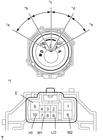
Text in Illustration *a off *b lo *c M1 *d M2 *e HI *f Component without harness connected
(No. 2 Heater Control Sub-assembly)
Measure the resistance according to the value(s) in the table below.
Standard Resistance Tester Connection Switch Condition Specified Condition ALL - 5 (E) 0 (OFF) 10 kΩ or higher 9 (LO) - 5 (E) 1 (LO) Below 1 Ω 9 (LO) - 5 (E) - 7 (M1) 1 (LO) - 2 (M1) Below 1 Ω 9 (LO) - 5 (E) - 7 (M1) 2 (M1) Below 1 Ω 9 (LO) - 5 (E) - 7 (M1) - 6 (M2) 2 (M1) - 3 (M2) Below 1 Ω 9 (LO) - 5 (E) - 6 (M2) 3 (M2) Below 1 Ω 9 (LO) - 5 (E) - 10 (HI) - 6 (M2) 3 (M2) - 4(HI) Below 1 Ω 9 (LO) - 5 (E) - 10 (HI) 4 (HI) Below 1 Ω
-
If the result is not as specified, replace the No. 2 heater control sub-assembly.
-
-
Check the illumination operation.
-
Connect the positive (+) lead from the battery to terminal 2 (ILL+) and the negative (-) lead to terminal 1 (ILL-), then check that the bulb illuminates.
OK Bulb illuminates
-
If the result is not as specified, replace the bulb.
-
-
-
-
INSPECT NO. 3 HEATER CONTROL SUB-ASSEMBLY
-
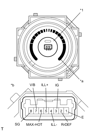
Text in Illustration *1 Rr Defogger Switch *a MAX HOT *b Component without harness connected
(No. 3 Heater Control Sub-assembly)
Measure the resistance according to the value(s) in the table below.
Standard Resistance Tester Connection Condition Specified Condition 2 (Rr DEF) - 1(E) Rear window defogger switch ON Below 1 Ω Rear window defogger switch OFF 10 kΩ or higher 3 (IG) - 6 (MAX-HOT) MAX HOT Below 1 Ω Except MAX HOT 10 kΩ or higher 7 (V/B) - 8 (SG) Always Below 1 Ω
-
If the result is not as specified, replace the No. 3 heater control sub-assembly.
-
-
Check the rear window defogger indicator operation.
-
Connect the positive (+) lead from the battery to terminal 3 (IG) and the negative (-) lead to terminal 1 (E).
-
Push the rear window defogger switch in and check that the indicator lights up.
OK Indicator lights up
-
If the result is not as specified, replace the No. 3 heater control sub-assembly.
-
-
-
Check the illumination operation.
-
Connect the positive (+) lead from the battery to terminal 5 (ILL+) and the negative (-) lead to terminal 4 (ILL-), and then check that the bulb illuminates.
OK Bulb illuminates
-
If the result is not as specified, replace the bulb.
-
-
-