LOWER INSTRUMENT PANEL INSTALLATION
PROCEDURE
-
INSTALL LOWER INSTRUMENT PANEL SUB-ASSEMBLY
-
Engage the 2 clips and install the lower instrument panel sub- assembly.
-
Install the 7 <B> bolts and 2 <C> bolts, <D> screw.
-
Connect each connector and engage the clamp.
-
Install the 2 clips.
-
Engage the 2 claws and the DLC 3 connector.
-
-
INSTALL ANTENNA CORD SUB-ASSEMBLY
-
CONNECT HOOD LOCK CONTROL LEVER SUB-ASSEMBLY
-
Engage the 3 claws and connect the hood lock control lever sub-assembly.
-
-
INSTALL NO. 1 INSTRUMENT PANEL BRACE MOUNTING BRACKET
-
Install the No. 1 instrument panel brace mounting bracket with the 2 screws.
-
-
INSTALL FLOOR SHIFT SHIFT LEVER ASSEMBLY (for Manual Transmission)
-
CONNECT TRANSMISSION CONTROL CABLE ASSEMBLY
-
INSTALL SHIFT LOCK CONTROL UNIT ASSEMBLY (for Multi-Mode Manual Transaxle)
-
INSTALL SHIFT LOCK CONTROL UNIT ASSEMBLY (for CVT)
-
INSTALL SHIFT LEVER KNOB SUB-ASSEMBLY (for Multi-Mode Manual Transaxle)
-
INSTALL SHIFT LEVER KNOB SUB-ASSEMBLY (for CVT)
-
INSTALL POWER OUTLET SOCKET COVER NO.2
-
INSTALL POWER OUTLET SOCKET ASSEMBLY
-
INSTALL LOWER INSTRUMENT PANEL CENTER FINISH PANEL
-
Engage the clamp and connect the connector.
-
Engage the 4 claws and 6 guides, install the lower center instrument panel finish panel.
-
Install the 2 screws.
-
-
INSTALL SHIFTING HOLE COVER SUB-ASSEMBLY (for Manual Transmission)
-
INSTALL CENTER INSTRUMENT CLUSTER FINISH PANEL ASSEMBLY
-
Engage the 4 clips and claws, and install the center instrument cluster finish panel assembly.
-
-
INSTALL SHIFT LEVER KNOB SUB-ASSEMBLY (for Manual Transaxle)
-
INSTALL NO. 1 STEREO JACK ADAPTER ASSEMBLY
-
INSTALL AIRBAG CUT-OFF SWITCH
-
INSTALL HEADLIGHT LEVELING SWITCH (for Halogen Headlight)
-
INSTALL SPARE SWITCH HOLE COVER (w/o Entry and Start System)
-
Engage the 2 claws and install the spare switch hole cover.
-
-
INSTALL ENGINE SWITCH (w/ Entry and Start System)
-
INSTALL OUTER MIRROR SWITCH ASSEMBLY
-
INSTALL NO. 2 LOWER INSTRUMENT PANEL FINISH PANEL (for LHD)
-
Engage the 5 clips, and install the No. 2 lower instrument panel finish panel.
-
-
INSTALL NO. 2 LOWER INSTRUMENT PANEL FINISH PANEL (for RHD)
-
Engage the 5 clips and guide, install the No. 2 lower instrument panel finish panel.
-
-
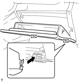
INSTALL GLOVE COMPARTMENT DOOR STOPPER SUB-ASSEMBLY
-
Engage the claw and install the glove compartment door stopper sub-assembly.
-
-
INSTALL GLOVE COMPARTMENT DOOR CHECK CUSHION
-
Install the 2 glove compartment door check cushions to the glove compartment door assembly.
-
-
INSTALL GLOVE COMPARTMENT DOOR ASSEMBLY
-
Horizontally engage the 2 hinges of the glove compartment door assembly.
Note
Make sure to install the glove compartment door assembly hinges horizontally.
-
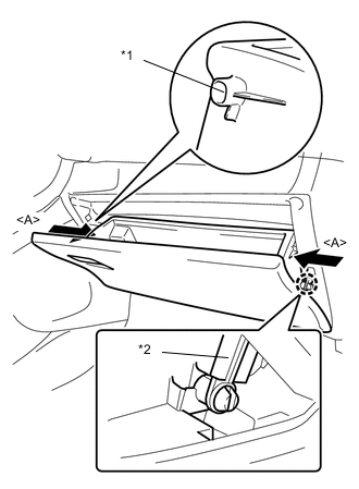
Engage the 2 stoppers by pushing the sections <A> indicated by the arrows.
-
Engage the claw and connect the glove compartment door stopper sub-assembly to install the glove compartment door .
Text in illustration *1 Stopper *2 Glove Compartment Door Stopper
-
-
INSTALL NO. 1 LOWER INSTRUMENT PANEL AIRBAG ASSEMBLY
-
INSTALL LOWER INSTRUMENT PANEL FINISH PANEL SUB-ASSEMBLY (for RHD)
-
Engage the 2 clips and 4 claws, and install the lower instrument panel finish panel sub-assembly.
-
-
INSTALL INSTRUMENT PANEL UNDER TRAY (for LHD)
-
Engage the clip and 7 claws, and install the instrument panel under tray.
-
-
INSTALL INSTRUMENT PANEL UNDER TRAY (for RHD)
-
Engage the 2 clips and 5 claws and install the instrument panel under tray.
-
-
CONNECT AIR INLET DAMPER CONTROL CABLE SUB-ASSEMBLY (for Manual Air Conditioning System)
-
CONNECT DEFROSTER DAMPER CONTROL CABLE SUB-ASSEMBLY (for Manual Air Conditioning System)
-
CONNECT AIRMIX DAMPER CONTROL CABLE SUB-ASSEMBLY (for Manual Air Conditioning System)
-
INSTALL LOWER INSTRUMENT CENTER CLUSTER FINISH PANEL SUB-ASSEMBLY (for Manual Air Conditioning System)
-
INSTALL AIR CONDITIONING CONTROL ASSEMBLY (for Automatic Air Conditioning System)
-
INSTALL NO. 1 INTERIOR ILLUMINATION LIGHT ASSEMBLY RH
-
INSTALL NO. 2 INSTRUMENT PANEL UNDER COVER SUB-ASSEMBLY
-
Engage the guide and the 3 claws, install the No. 2 instrument panel under cover sub-assembly.
-
-
INSTALL NO. 1 INTERIOR ILLUMINATION LIGHT ASSEMBLY LH
-
INSTALL NO. 1 INSTRUMENT PANEL UNDER COVER SUB-ASSEMBLY
-
Engage the guide and 2 claws, install the No. 1 instrument panel under cover sub-assembly.
-
Install the 2 screws.
-
-
INSTALL HEADLIGHT DIMMER SWITCH ASSEMBLY
-
INSTALL REAR CONSOLE BOX ASSEMBLY
-
INSTALL UPPER INSTRUMENT PANEL
-
CONNECT CABLE TO NEGATIVE BATTERY TERMINAL
- Torque:
- 5.4 N*m { 55 kgf*cm, 48 in.*lbf }
Note
When disconnecting the cable, some systems need to be initialized after the cable is reconnected Click here.
-
CHECK SRS WARNING LIGHT