LOWER INSTRUMENT PANEL REMOVAL
PROCEDURE
-
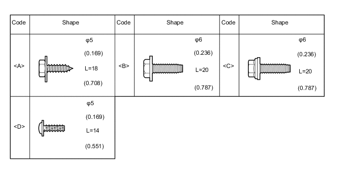
TABLE OF BOLT, SCREW AND NUT
Tech Tips
All bolts, screws and nuts relevant to installing and removing the instrument panel are shown along with their alphabet code in the table below.
-
DISCONNECT CABLE FROM NEGATIVE BATTERY TERMINAL
CAUTION:
Wait at least 90 seconds after disconnecting the cable from the negative (-) battery terminal to disable the SRS system.
Note
When disconnecting the cable, some systems need to be initialized after the cable is reconnected Click here.
-
FRONT WHEELS FACING STRAIGHT AHEAD
-
REMOVE UPPER INSTRUMENT PANEL
-
REMOVE REAR CONSOLE BOX ASSEMBLY
-
REMOVE HEADLIGHT DIMMER SWITCH ASSEMBLY
-
REMOVE STEREO OPENING COVER WITH BRACKET (w/o Audio)
-
Remove the 4 screws and the stereo opening cover with bracket.
-
Disengage the clamp to disconnect the antenna connector.
-
-
REMOVE NO. 1 RADIO BRACKET (w/o Audio)
-
Remove the 4 screws and the No. 1 radio bracket from the stereo opening cover.
-
-
REMOVE NO. 2 RADIO BRACKET (w/o Audio)
-
Remove the 4 screws and the No. 2 radio bracket from the stereo opening cover.
-
-
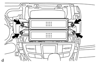
REMOVE NO. 1 INSTRUMENT PANEL UNDER COVER SUB-ASSEMBLY
-
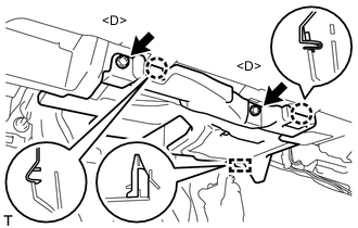
Remove the 2 <D> screws.
-
Disengage the guide and 2 claws to remove the No. 1 instrument panel under cover sub-assembly.
-
-
REMOVE NO. 1 INTERIOR ILLUMINATION LIGHT ASSEMBLY LH
-
REMOVE TIRE PRESSURE WARNING RESET SWITCH (except 1NZ-FE)
-
REMOVE NO. 2 INSTRUMENT PANEL UNDER COVER SUB-ASSEMBLY
-
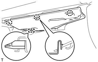
Disengage the guide and the 3 claws to remove the No. 2 instrument panel under cover sub-assembly.
-
-
REMOVE NO. 1 INTERIOR ILLUMINATION LIGHT ASSEMBLY RH
-
REMOVE AIR CONDITIONING CONTROL ASSEMBLY (for Automatic Air Conditioning System)
-
REMOVE LOWER INSTRUMENT CENTER CLUSTER FINISH PANEL SUB-ASSEMBLY (for Manual Air Conditioning System)
-
DISCONNECT AIRMIX DAMPER CONTROL CABLE SUB-ASSEMBLY (for Manual Air Conditioning System)
-
DISCONNECT DEFROSTER DAMPER CONTROL CABLE SUB-ASSEMBLY (for Manual Air Conditioning System)
-
DISCONNECT AIR INLET DAMPER CONTROL CABLE SUB-ASSEMBLY (for Manual Air Conditioning System)
-
REMOVE INSTRUMENT PANEL UNDER TRAY (w/ Knee Airbag)
-
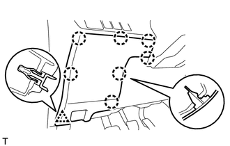
Disengage the clip and 7 claws to remove the instrument panel under tray.
-
-
REMOVE INSTRUMENT PANEL UNDER TRAY (w/o Knee Airbag)
-
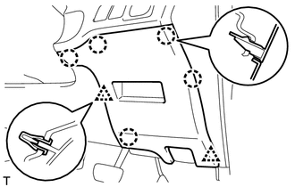
Disengage the 2 clips and 5 claws to remove the instrument panel under tray.
-
-
REMOVE NO. 1 LOWER INSTRUMENT PANEL AIRBAG ASSEMBLY (w/ Knee Airbag)
-
REMOVE LOWER INSTRUMENT PANEL FINISH PANEL SUB-ASSEMBLY (w/o Knee Airbag)
-
Disengage the 2 clips and 4 claws to remove the lower instrument panel finish panel sub-assembly.
-
-
REMOVE GLOVE COMPARTMENT DOOR ASSEMBLY
-
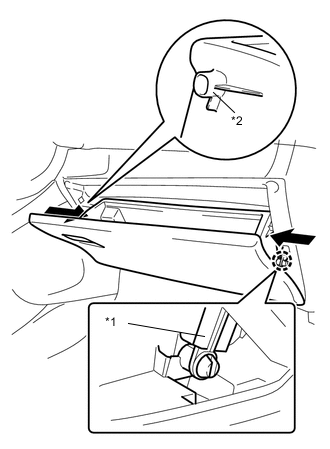
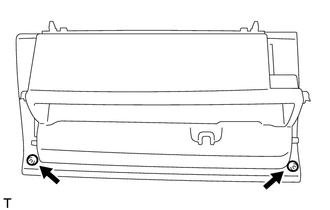
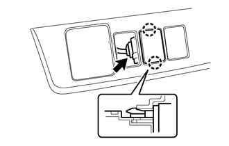
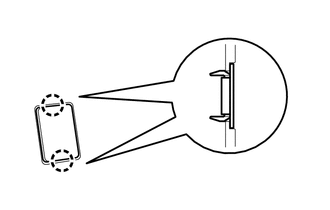
Disengage the claw to release the glove compartment door stopper sub-assembly.
-
Push the sections indicated by the arrows to release the 2 stoppers and open the outer glove compartment door until it is horizontal.
Text in Illustration *1 Glove Compartment Door Stopper Sub-assembly *2 Stopper -
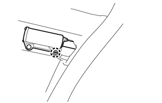
Pull the glove compartment door assembly horizontally backward to disengage the 2 hinges and remove the glove compartment door assembly.
Note
Be sure to pull the outer glove compartment door horizontally to remove it.
-
-
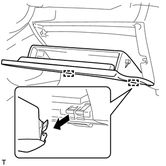
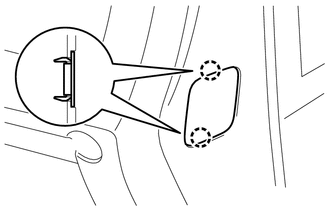
REMOVE GLOVE COMPARTMENT DOOR CHECK CUSHION
-
Remove the 2 glove compartment door check cushions from the glove compartment door assembly.
-
-
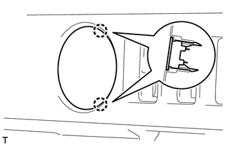
REMOVE GLOVE COMPARTMENT DOOR STOPPER SUB-ASSEMBLY
-
Disengage the claw to remove the glove compartment door stopper sub-assembly.
-
-
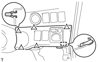
REMOVE NO. 2 LOWER INSTRUMENT PANEL FINISH PANEL (for LHD)
-
Disengage the 3 clips and 3 guides to remove the No. 2 lower instrument panel finish panel.
-
-
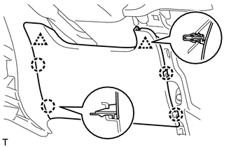
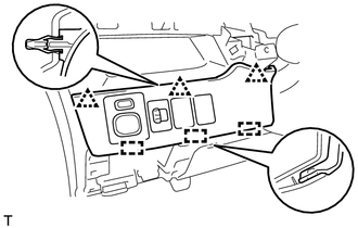
REMOVE NO. 2 LOWER INSTRUMENT PANEL FINISH PANEL (for RHD)
-
Disengage the 5 clips and guide to remove the No. 2 lower instrument panel finish panel.
-
-
REMOVE OUTER MIRROR SWITCH ASSEMBLY
-
REMOVE VSC OFF SWITCH
-
REMOVE HEADLIGHT LEVELING SWITCH (for Halogen Headlight)
-
REMOVE HEATER SWITCH ASSEMBLY (w/ Combustion Type Power Heater)
-
Disconnect the 2 claws to remove the heater switch assembly.
-
Disconnect the connector.
-
-
REMOVE ENGINE SWITCH (w/ Entry and Start System)
-
REMOVE SPARE SWITCH HOLE COVER (w/o Entry and Start System)
-
Disengage the 2 claws to remove the spare switch hole cover.
-
-
REMOVE PATTERN SELECT SWITCH ASSEMBLY (for 1NZ-FE)
-
REMOVE AIRBAG CUT-OFF SWITCH (w/ Knee Airbag)
-
REMOVE INSTRUMENT PANEL HOLE COVER (w/o Knee Airbag)
-
Disengage the 2 claws to remove the instrument panel hole cover.
-
-
REMOVE NO. 1 STEREO JACK ADAPTER ASSEMBLY (w/ Audio)
-
REMOVE SHIFT LEVER KNOB SUB-ASSEMBLY (for Manual Transaxle)
-
REMOVE CENTER INSTRUMENT CLUSTER FINISH PANEL ASSEMBLY
-
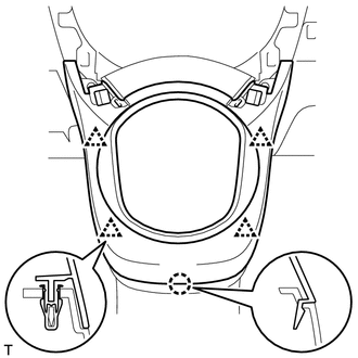
Disengage the 4 clips and claw to remove the center instrument cluster finish panel assembly.
-
-
REMOVE SHIFTING HOLE COVER SUB-ASSEMBLY (for Manual Transaxle)
-
REMOVE LOWER INSTRUMENT PANEL CENTER FINISH PANEL
-
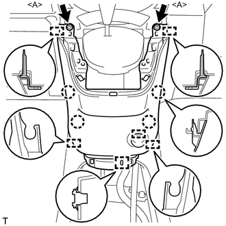
Remove the 2 <A> screws.
-
Disengage the 4 claws and 6 guides to remove the lower instrument panel center finish panel.
-
Disengage the clamp to disconnect the connector.
-
-
REMOVE POWER OUTLET SOCKET ASSEMBLY
-
REMOVE NO. 2 POWER OUTLET SOCKET COVER
-
REMOVE SHIFT LEVER KNOB SUB-ASSEMBLY (for CVT)
-
REMOVE SHIFT LOCK CONTROL UNIT ASSEMBLY (for CVT)
-
DISCONNECT TRANSMISSION CONTROL CABLE ASSEMBLY (for Manual Transaxle)
-
REMOVE SHIFT LEVER ASSEMBLY (for Manual Transaxle)
-
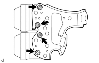
REMOVE NO. 1 INSTRUMENT PANEL BRACE MOUNTING BRACKET
-
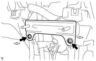
Remove the 2 <D> screws and No. 1 instrument panel brace mounting bracket.
-
-
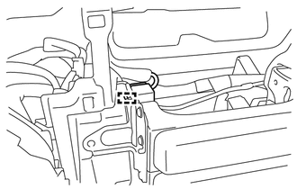
DISCONNECT HOOD LOCK CONTROL LEVER SUB-ASSEMBLY
-
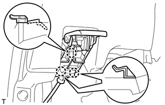
Disengage the 3 claws to disconnect the hood lock control lever sub-assembly.
-
-
REMOVE ANTENNA CORD SUB-ASSEMBLY
-
REMOVE LOWER INSTRUMENT PANEL SUB-ASSEMBLY
-
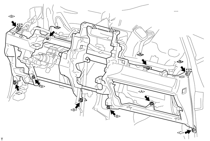
Disengage the 2 claws to disconnect the DLC3 connector.
-
Disconnect each connector and disengage each clamp.
-
Remove the 2 clips.
-
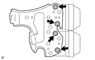
Remove the <A> screw, 7 <B> bolts and 2 <C> bolts.
-
Disengage the 2 guides to remove the lower instrument panel sub-assembly.
-
-
REMOVE SPARE SWITCH HOLE COVER
-
Disengage the 2 claws to remove the spare switch hole cover.
-
-
REMOVE NO. 1 INSTRUMENT PANEL SAFETY PAD (for 1NZ-FE)
-
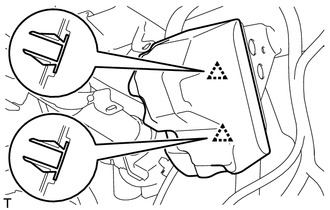
Disengage the 2 clips to remove the No. 1 instrument panel safety pad.
-
-
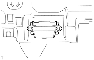
REMOVE NO. 2 INSTRUMENT PANEL SAFETY PAD (for 1NZ-FE)
Tech Tips
Use the same procedure as for the No. 1 instrument panel safety pad.