COMPRESSOR(for 1ND-TV) INSTALLATION
PROCEDURE
-
ADJUST COMPRESSOR OIL
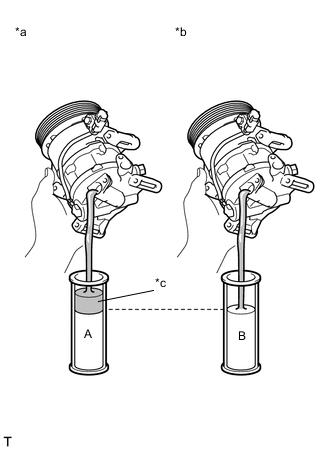
Text in Illustration *a New Compressor Assembly With Pulley *b Removed Compressor Assembly With Pulley *c Drain Extra Oil (A - B)
-
When replacing the compressor assembly with pulley with a new one, gradually discharge the refrigerant gas (helium) from the service valve. Then drain the following amount of oil from the new compressor assembly with pulley before installation, so that the amount of oil contained in it is the same as that in the compressor assembly with pulley to be replaced.
Tech Tips
New compressor assembly with pulley are filled with sufficient oil for the whole cycle. Therefore, it is necessary to drain residual oil from the condenser and cooling unit.
Standard (The amount of compressor oil inside a new compressor: 60 (+15) cc (2.0 (+0.51) fl.oz.)) - (The amount of compressor oil remaining in the removed compressor) = The amount of compressor oil to be removed when replacing the compressor assembly with pulley Note
-
When checking the compressor oil level, observe the precautions for cooler removal/installation.
-
If a new compressor assembly with pulley is installed without removing the same amount of compressor oil as is remaining in the pipes, the amount of compressor oil will be excessive. This prevents heat exchange in the refrigerant cycle and will cause a refrigeration failure.
-
If the amount of compressor oil remaining in the removed compressor assembly with pulley is too low, check for compressor oil leakage.
-
Use ND-OIL8 or equivalent for compressor oil.
-
-
If draining the compressor oil is difficult, drain the compressor oil using the following procedure:
-
Rotate the pulley, and drain the compressor oil.
Note
-
Do not allow the pulley to come into contact with the compressor oil.
-
If the pulley is rotated, refrigerant or compressor oil might splash out. Thus, keep your face away from the compressor port.
-
-
-
-
INSTALL COMPRESSOR ASSEMBLY WITH PULLEY
-
Using a "TORX" socket wrench (E8), install the compressor assembly with pulley with the 2 stud bolts.
- Torque:
- 15 N*m { 153 kgf*cm, 11 ft.*lbf }
-
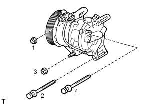
Install the compressor assembly with pulley with the 2 bolts and the 2 nuts.
Tech Tips
Tighten the bolts and the nuts in the order shown in the illustration.
- Torque:
- 25 N*m { 250 kgf*cm, 18 ft.*lbf }
-
Connect the connector.
-
-
CONNECT NO. 1 COOLER REFRIGERANT DISCHARGE HOSE
-
Remove the attached vinyl tape from the hose.
-
Apply sufficient compressor oil to a new O-ring and the fitting surface of the compressor assembly with pulley.
Compressor oil ND-OIL8 or equivalent -
Install the O-ring onto the discharge hose.
-
Install the discharge hose onto the compressor with the bolt.
- Torque:
- 9.8 N*m { 100 kgf*cm, 87 in.*lbf }
-
-
CONNECT SUCTION HOSE
-
Remove the attached vinyl tape from the suction hose.
-
Apply sufficient compressor oil to a new O-ring and the fitting surface of the compressor assembly with pulley.
Compressor oil ND-OIL8 or equivalent -
Install the O-ring onto the suction hose.
-
Install the suction hose onto the compressor assembly with pulley with the bolt.
- Torque:
- 9.8 N*m { 100 kgf*cm, 87 in.*lbf }
-
-
INSTALL FAN AND GENERATOR V BELT
-
CONNECT CABLE TO NEGATIVE BATTERY TERMINAL
- Torque:
- 5.4 N*m { 55 kgf*cm, 48 in.*lbf }
-
INSTALL FRONT BUMPER COVER
-
CHARGE REFRIGERANT
-
WARM UP ENGINE
-
INSPECT FOR REFRIGERANT LEAK
-
INSPECT SRS WARNING LIGHT