AIR CONDITIONING UNIT REASSEMBLY
PROCEDURE
-
INSTALL NO. 1 COOLER THERMISTOR
-
INSTALL NO. 1 COOLER EVAPORATOR SUB-ASSEMBLY
-
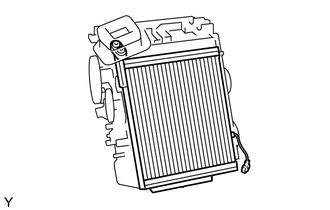
Install the No. 1 cooler evaporator sub-assembly.
Tech Tips
If a new cooler evaporator sub-assembly is installed, add compressor oil to the cooler evaporator sub-assembly as follows.
Capacity Add 40 cc (1.35 fl. oz.) Compressor oil ND-OIL8 or equivalent. -
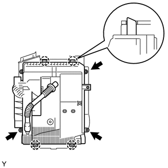
Engage the 4 claws and install the lower heater case.
-
Install the 3 screws.
-
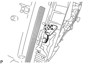
Engage the No. 1 cooler thermistor connector clamp.
-
-
INSTALL DRAIN COOLER HOSE
-
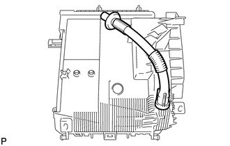
Install the drain cooler hose.
-
-
INSTALL COOLER EXPANSION VALVE
-
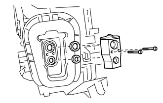
Apply sufficient compressor oil to new 2 O-rings and the fitting surfaces of the cooler expansion valve.
Compressor oil ND-OIL8 or equivalent -
Install the 2 O-rings onto the No. 1 cooler evaporator sub-assembly.
-
Using a 4 mm hexagon wrench, install the cooler expansion valve with the 2 hexagon bolts.
- Torque:
- 3.5 N*m { 36 kgf*cm, 31 in.*lbf }
-
-
INSTALL HEATER RADIATOR UNIT SUB-ASSEMBLY
-
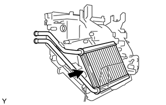
Install the heater radiator unit sub-assembly onto the air conditioning unit.
-
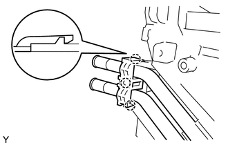
Engage the 3 claws and install the clamp.
-
-
INSTALL QUICK HEATER ASSEMBLY
-
INSTALL ASPIRATOR PIPE (for Automatic Air Conditioning System)
-
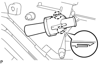
Engage the 2 claws and install the aspirator pipe.
-
-
INSTALL NO. 2 AIR DUCT
-
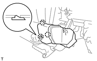
Engage the 3 claws and install the No. 2 air duct.
-
-
INSTALL NO. 1 AIR DUCT
-
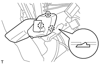
Engage the 3 claws and install the No. 1 air duct.
-
-
INSTALL COOLER (DUCT SENSOR) THERMISTOR (for Engine Stop and Start System)
-
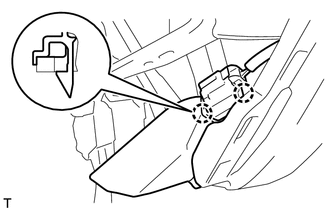
Engage the 2 claws and install the cooler (duct sensor) thermistor.
-
-
INSTALL AIR MIX DAMPER CONTROL CABLE SUB-ASSEMBLY (for Manual Air Conditioning System)
-
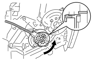
Text in Illustration *a MAX COOL position Align the air mix damper control cable sub-assembly in the MAX COOL position.
-
Engage the 3 claws and install the air mix damper control cable sub-assembly.
-
-
INSTALL AIR MIX DAMPER SERVO SUB-ASSEMBLY (for Automatic Air Conditioning System)
-
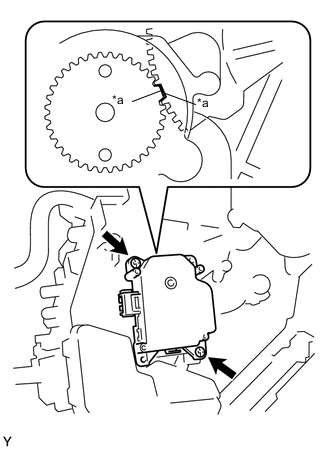
Text in Illustration *a Reference Position Align the reference position, and then install the air mix damper servo sub-assembly.
-
Tighten the 2 screws.
-
-
INSTALL MODE DAMPER SERVO SUB-ASSEMBLY (for Automatic Air Conditioning System)
-
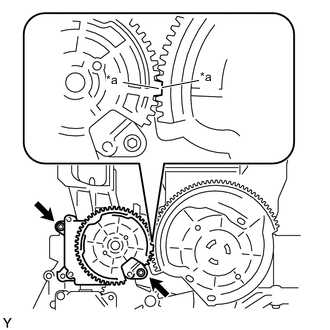
Text in Illustration *a Reference Position Align the reference position, and then install the mode damper servo sub-assembly.
-
Install the 2 screws.
-
-
INSTALL DEFROSTER DAMPER CONTROL CABLE SUB-ASSEMBLY (for Manual Air Conditioning System)
-
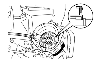
Text in Illustration *a FACE position Align the defroster damper control cable sub-assembly in the FACE position.
-
Engage the 3 claws and install the defroster damper control cable sub-assembly.
-