COMBUSTION TYPE POWER HEATER SYSTEM ECU Power Source Circuit
DESCRIPTION
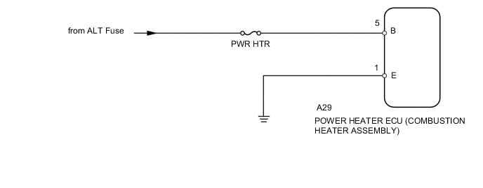
This is the power source for the power heater ECU (combustion heater assembly).
WIRING DIAGRAM
CAUTION / NOTICE / HINT
Note
Inspect the fuses for circuits related to this system before performing the following inspection procedure.
Tech Tips
Before performing the following procedure, check the battery and generator and confirm that they are operating normally.
PROCEDURE
-
CHECK HARNESS AND CONNECTOR (POWER HEATER ECU (COMBUSTION HEATER ASSEMBLY) - BODY GROUND)
-
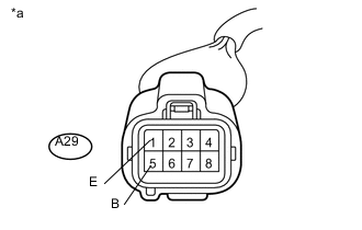
Text in Illustration *a Front view of wire harness connector
(to Power Heater ECU (Combustion Heater Assembly))
Disconnect the A29 power heater ECU (combustion heater assembly) connector.
-
Measure the voltage according to the value(s) in the table below.
Standard Voltage Tester Connection Condition Specified Condition A29-5 (B) - Body ground Always 11 to 14 V -
Measure the resistance according to the value(s) in the table below.
Standard Resistance Tester Connection Condition Specified Condition A29-1 (E) - Body ground Always Below 1 Ω -
Reconnect the power heater ECU (combustion heater assembly) connector.
OK 
PROCEED TO NEXT SUSPECTED AREA SHOWN IN PROBLEM SYMPTOMS TABLE Click here
NG
REPAIR OR REPLACE HARNESS OR CONNECTOR
-